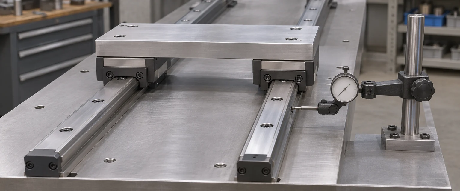
Measure linear rail parallelism by moving a repeatable reference along one established rail and recording the relative position of the second rail. Check lateral separation and height difference separately, then repeat after final tightening. A carriage that travels freely is useful evidence of assembly condition, but it is not a numerical parallelism measurement.
For a two-rail OEM axis, the aim is to produce a trace that another assembler can reproduce. The master rail, measuring face, indicator direction, measurement stations and tightening state all need to be defined before collecting readings.
Decide which relationship you are measuring
Three checks are often confused: rail-to-rail lateral alignment, rail mounting-height difference, and the running accuracy of a carriage. They describe different relationships.
| Check | Typical contact direction | What the result describes |
|---|---|---|
| Relative lateral alignment | Indicator normal to a designated side face | Change in separation along travel |
| Relative height | Indicator normal to a designated upper reference surface | Change in relative height |
| Carriage running accuracy | Indicator or optical measurement against an independent reference | Motion of the carriage relative to that reference |
Choose the permitted measuring surfaces from the guide documentation. A seal, bolt cap or unfinished edge is not a substitute for a specified reference face. Also distinguish installation tolerances from catalog running-accuracy figures. HIWIN’s official guideway catalog ties accuracy definitions to particular surfaces and measurement conditions; those conditions matter as much as the numerical grade.
Establish the master rail first
Confirm the master rail’s seating, fastening and alignment to the machine datum. If it is bowed or mounted on debris, using it as the measurement reference transfers that condition into the result.
A stiff indicator bracket can travel with a carriage on the master rail and contact the designated surface of the second rail. Keep the bracket short and the contact geometry consistent. Where practicable, compare results with an independent straightedge or suitable optical system. An indicator trace referenced to one rail cannot by itself prove that both rails are straight in machine coordinates.
For a base with locating shoulders, resolve shoulder contact and corner clearance before spending time on alignment corrections.
Collect a trace that can be repeated
Use a controlled measurement sequence suited to the equipment:
- Clean the measurement surfaces and stabilize the assembly’s temperature.
- Establish the master rail and fit a rigid measuring bracket without distorting the carriage.
- Set the indicator near its intended working orientation and record the zero station.
- Measure at identified stations through the usable travel, including between mounting bolts.
- Return along the same route and record a second trace.
- Repeat after the approved final bolt-tightening sequence.
Use enough stations to reveal local errors; endpoints alone can miss a high spot in the middle. Approach each station consistently and allow the indicator to settle. Record the zero return at the end of the sweep so bracket movement is visible.
Do not use a rigid table bridging both rails to force a misaligned second rail into place and then call the resulting low drag a measurement. The bridge, blocks and base can deflect together.
A measurement log with an explicit calculation
The following readings are an invented demonstration of the calculation, not an acceptance limit or a LIMON test report.
| Station, mm | Lateral reading, µm | Return reading, µm |
|---|---|---|
| 0 | 0 | 1 |
| 100 | 4 | 5 |
| 200 | 9 | 10 |
| 300 | 6 | 7 |
| 400 | 2 | 3 |
For the outward sweep, the relative lateral variation is the maximum reading minus the minimum reading: 9 − 0 = 9 µm. Keep the actual trace, rather than reporting only this range. The location of the peak helps distinguish a local seating problem from a steadily changing separation.
The return readings are offset by approximately 1 µm in this example. Investigate zero return, contact hysteresis and bracket stability before interpreting differences of that order as rail movement. A tolerance comparable to measurement uncertainty needs a more capable measurement arrangement.
Interpret the shape before adjusting the rail
A steadily increasing trace may indicate angular misalignment. A local peak near a bolt can point to a seating or fastening issue. A difference between outward and return traces can arise from measuring-fixture movement, contact behavior or carriage motion. These are diagnostic leads, not proof of a single cause.
Check whether the error remains at the same physical position when the bracket is reinstalled. If the trace changes substantially with the measuring setup, improve the setup before moving the rail. Record both lateral and vertical results; correcting one can affect the other.
Which tolerance should the assembly meet?
Use the selected manufacturer’s installation limits for the actual series, size and preload, together with the machine’s accuracy requirement. There is no universal rail-parallelism tolerance that is appropriate for every guide and base.
A useful handover record includes rail identities, preload class, mounting orientation, load state, temperatures, indicator resolution, bracket position, measurement stations, bolt state and raw readings. Keep the acceptance criterion next to the result and identify its source.
For a paired LIMON linear guideway enquiry, send rail length, rail spacing, carriage arrangement, base drawing and required accuracy. The catalog download page and LIMON contact team are the next steps for confirming the model-specific installation requirements.