A part can sit well below a rotary platform's axial load limit and still put too much overturning moment on its output bearing. The weight is only one input. Where the center of mass sits, where the process pushes, and how the table accelerates all change the loads that reach the platform.
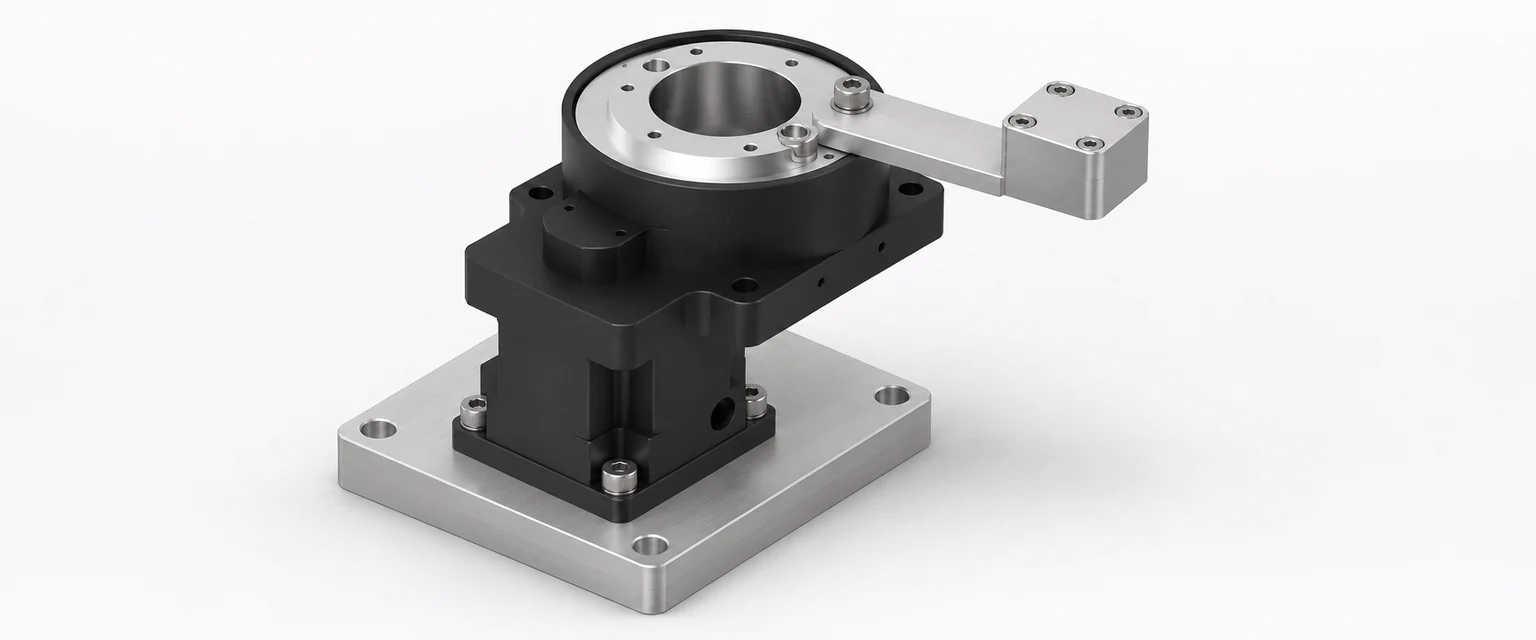
Separate the loads at the output face
| Quantity | Where it acts | Example on a rotary fixture |
|---|---|---|
| Axial or thrust load | Along the rotation axis | Weight on a horizontal table with a vertical rotation axis |
| Radial load | Perpendicular to the rotation axis | Side force from a tool or the radial force from an off-center moving mass |
| Overturning moment | About an axis in the plane of the output face | An offset downward load that tends to tip the table |
| Drive torque | About the rotation axis | Torque needed to accelerate the fixture or overcome a tangential process force |
Moment and torque both use N·m. They go into different checks. A large permissible drive torque tells you little about the output bearing's tolerance for a tilting load. For example, the Oriental Motor DGII specifications list permissible torque and permissible moment separately. Use the model-specific load conditions when reviewing any candidate.
What an offset fixture adds
Consider a stationary platform with a horizontal output face. In this example, the fixture and part have a combined mass of 10 kg, and their center of mass is 0.16 m from the rotation axis. Their weight puts about 98 N of axial load on the table. The offset produces 98 × 0.16 ≈ 15.7 N·m of overturning moment. Gravity produces no drive torque about this vertical axis.
Now suppose the machine applies a horizontal force of 40 N whose line is 0.12 m above the face. That adds 40 N of radial load and 4.8 N·m of overturning moment about a horizontal axis. If the two moments act in the same direction in that station, their combined magnitude is about 20.5 N·m. If the directions differ, combine their components from the force diagram. A tangential process force can also create drive torque about the rotation axis, depending on its line of action in plan view.
The same fixture on a table with a horizontal rotation axis has a different gravity load. Its weight is then radial, and the gravity torque can vary with angular position if the mass is off center. Mark the intended orientation on the drawing before sizing the platform.
Check the move and the mounting as well as the dwell
At speed, the bearing also reacts the radial component associated with accelerating an eccentric mass around the rotation axis. During changes in speed, the drive must supply acceleration torque. Use the actual fixture and part inertia about the output axis for that check. A centered estimate based only on mass can understate the effect of a heavy part carried well away from the center.
Identify which loads occur together at each station, during indexing and during the process dwell. Send that combined load case to the manufacturer. Individual catalog maxima may be specified under different conditions. Ask how the selected model should be checked under the simultaneous axial, radial and moment loads, with the required speed and duty cycle.
The output bearing also depends on its mounting. Review the bolted joint and base stiffness with the expected overhang. A flexible fixture or base can tilt under load before the drive torque limit is reached. If tool alignment matters, measure deflection at the point where the process acts and with the load applied in the relevant direction.
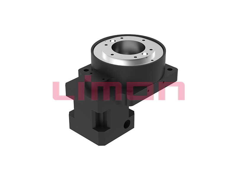
For a LIMON hollow rotary actuator enquiry, include the mounting orientation, fixture sketch, mass center, inertia if available, applied forces and their locations, index angle and timing. The DYH series page identifies the family and mounting variants. Send the load cases with the selection enquiry so the configuration can be checked against the actual job.