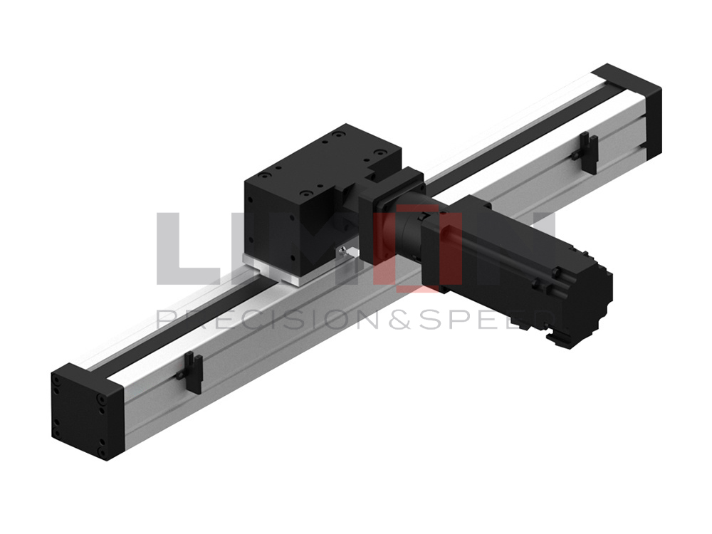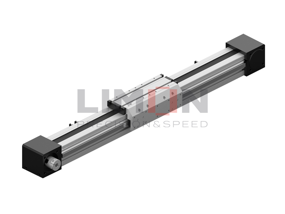
Incorrect linear guide load calculations can lead to premature failures, costly downtime, and reduced machine accuracy. Proper load capacity analysis ensures reliable performance, longer service life, and optimal system efficiency.
Linear guide load capacity calculation determines whether a guideway can safely support operational forces while maintaining accuracy and service life. By evaluating dynamic load, static load, moment loads, and operating conditions, engineers can select the most suitable linear guide for high-performance automation, CNC machinery, semiconductor equipment, and industrial applications.
Choosing the correct load capacity is the foundation of a reliable linear motion system.
What Is Linear Guide Load Capacity?
Linear guide load capacity refers to the maximum load a linear guide can support while maintaining smooth motion, accuracy, and expected service life. It is one of the most important factors when selecting a guideway for industrial automation systems.
A properly sized linear guide can:
- Improve machine stability
- Increase positioning accuracy
- Reduce maintenance costs
- Extend service life
- Prevent unexpected equipment failures
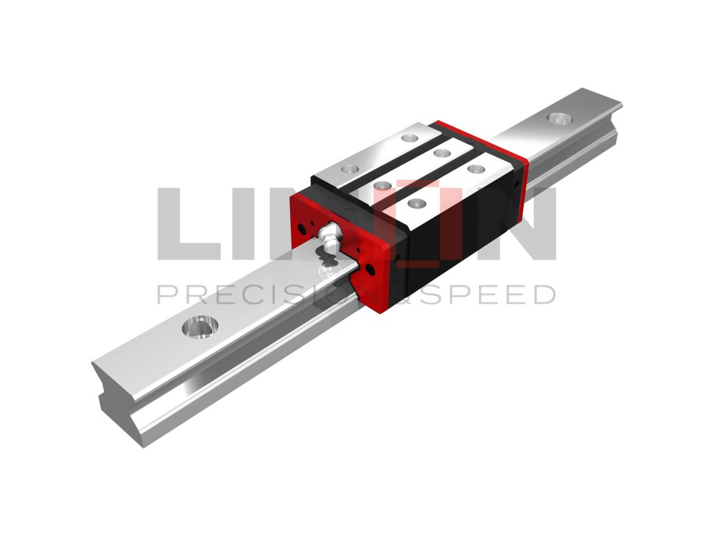
LIMON linear guideways feature four-row contact designs that provide high rigidity and equal load ratings in radial, reverse radial, and lateral directions, making them suitable for demanding industrial applications.
Types of Loads Acting on a Linear Guide
Before calculating load capacity, engineers must understand the different forces acting on the guide.
Radial Load
A radial load acts perpendicular to the rail surface and is the most common load type in linear motion systems.
Reverse Radial Load
This load acts in the opposite direction of the radial load and is common in vertically mounted systems.
Lateral Load
Lateral loads act from the side of the guideway and are often generated during high-speed motion or directional changes.
Moment Loads
Moment loads occur when the load center is offset from the guide centerline, creating rotational forces.
The three primary moment types include:
- Pitch Moment (Mp)
- Roll Moment (Mr)
- Yaw Moment (My)
These moments must be included in load calculations to prevent uneven wear and premature failure.
Dynamic Load Capacity Calculation
Dynamic load rating represents the maximum load a linear guide can continuously support while achieving its rated service life.
The basic life equation is:
[L = \left(\frac{C}{P}\right)^3 \times 50
]
Where:
- L = Rated life (km)
- C = Basic dynamic load rating (N)
- P = Equivalent applied load (N)
This equation allows engineers to estimate the operating life of a guideway under a specific load condition.
Example
Assume:
- Dynamic load rating (C) = 20,000 N
- Applied load (P) = 10,000 N
Calculation:
[L = \left(\frac{20000}{10000}\right)^3 \times 50
] [
L = 8 \times 50
] [
L = 400\ km
]
This means the guideway is expected to achieve approximately 400 km of travel under the specified load.
Static Load Capacity Calculation
Static load capacity measures the maximum load a guide can withstand without permanent deformation.
The static safety factor is calculated as:
[f_s = \frac{C_0}{P_0}
]
Where:
- fs = Static safety factor
- C0 = Basic static load rating
- P0 = Maximum applied load
Typical safety factor recommendations are:
| Application | Safety Factor |
|---|---|
| Normal operation | 1.0 – 2.0 |
| Moderate vibration | 2.0 – 3.0 |
| Heavy impact loads | 3.0 – 5.0 |
Selecting an appropriate safety factor helps prevent raceway deformation and maintains long-term accuracy.
Calculating Equivalent Load
In most applications, loads act in multiple directions simultaneously.
The equivalent load can be estimated using:
[P = XF_r + YF_a
]
Where:
- P = Equivalent load
- Fr = Radial load
- Fa = Axial load
- X, Y = Manufacturer correction factors
Equivalent load calculations provide a more realistic assessment of actual operating conditions.
Influence of Guide Design on Load Capacity
Linear guide design directly affects load performance.
Four-Row Ball Guide Design
LIMON H Series linear guideways utilize a four-row ball contact structure that provides:
- Equal load ratings in all directions
- High rigidity
- Smooth operation
- Excellent self-aligning capability
This design can compensate for installation errors and improve system reliability.
Roller-Type Linear Guides
For heavy-duty applications, LIMON R Series linear guideways use rollers instead of balls.
Advantages include:
- Larger contact area
- Higher load capacity
- Greater rigidity
- Longer operating life
Compared with conventional ball-type guides, roller guides can support significantly higher loads while maintaining compact dimensions.
Factors Affecting Actual Load Capacity
Even when calculations are correct, real-world conditions influence performance.
Installation Accuracy
Misalignment can generate additional forces and reduce service life.
Lubrication
Insufficient lubrication increases friction, heat generation, and wear.
Operating Speed
High-speed applications create dynamic forces that may exceed theoretical calculations.
Environmental Conditions
Dust, moisture, and contaminants can accelerate component degradation.
LIMON offers pre-lubricated guideways and low-noise SynchMotion technology in QH and QE series products to enhance durability and reduce maintenance frequency.
Selecting the Right Linear Guide
When choosing a linear guide, engineers should evaluate:
- Load direction
- Maximum load value
- Required service life
- Moment loads
- Installation space
- Speed requirements
- Environmental conditions
For general industrial automation, H and E series guideways provide an excellent balance of rigidity and cost efficiency.
For high-speed, low-noise environments such as semiconductor equipment, QH and QE series are ideal.
For heavy-load CNC machining centers and cutting equipment, R series roller guides provide superior load capacity and stiffness.
Conclusion
Proper linear guide load capacity calculation ensures reliable performance, longer service life, and optimal machine accuracy in demanding industrial applications.