The first sign of a bad rail joint can be a brief rise in carriage resistance at one point in an otherwise smooth stroke. Treat that point as its own inspection station. A reading averaged over the full rail can hide a small step or sideways shift where two sections meet.
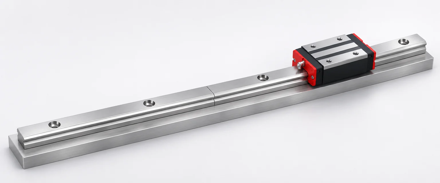
Keep the mating sections together
Start with the drawing or packing record for the complete rail set. Identify each rail line, the order of its sections, the datum side and the marks on the ends that meet. Put that information on the installation traveler before moving the sections to the machine. A match mark may identify a particular mating pair and direction. Two spare segments of the same nominal profile may have different end preparation or hole locations.
THK's joint rail instructions illustrate how a matched set can use mirrored rail lines and call for particular attention to support around the seam. Use the joint map supplied for your set, especially when the two lines have different left and right orientations. Record the joint positions so the team doing final inspection can find them after the carriage and covers are fitted.
Check the bed and the joint in two directions
Inspect the mounting face and datum near each seam, including the joint between base sections on machines shipped in pieces. A rail that bridges a low spot can look aligned until a loaded block passes over it. Look for burrs, incomplete contact and fasteners that reach the bottom of their holes before clamping the rail. The installation drawing should identify where the rail must be supported and how the joint ends are restrained.
Set up an indicator on a stable reference. Measure close to each end face on the same accessible top reference surface, with the probe clear of the edge relief. Repeat the comparison on the specified side reference surface. The top reading checks a height step. The side reading checks lateral offset. Sweep farther back on each section as well. A short step at the junction and a gradual slope through one whole section require different corrections. Use the supplier's specified reference surfaces and limits for acceptance.
| Keep in the joint record | How it helps later |
|---|---|
| Rail line, section marks and seam position | Makes the same joint identifiable after assembly |
| Height and side readings before and after final tightening | Shows whether a shift came from seating or fastening |
| Short sweeps either side of the seam | Distinguishes a step from a bend or change of direction |
| Traverse direction, load and speed used for the motion check | Lets the next team repeat a meaningful comparison |
On a two-rail table, verify the complete master line first. Then check how the second line follows it. The dual-rail parallelism guide covers the full-length measurement. A pair of parallel rails still needs an individual check at each seam. On an extrusion or segmented bed, the aluminum base mounting guide explains which readings to repeat after fitting the carriage and payload.
Check carriage resistance at the first traverse
With the rails fastened and lubricated according to their instructions, use the approved commissioning condition to cross each seam at low speed. Compare behavior on approach, across the joint and just beyond it, in both directions. Stop if there is a sharp rise in resistance and inspect the alignment and support before continuing. Grinding or stoning a rolling raceway in place can alter its geometry. If an end appears damaged or mismatch remains after seating, send the measurements and photos to the supplier for review.
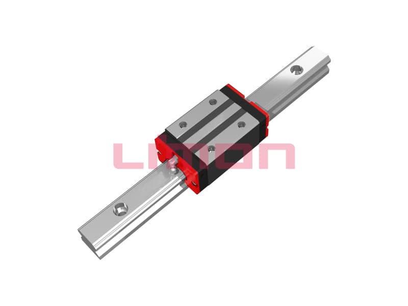
For a joined linear guideway enquiry, send the overall rail length, shipping section limit, rail layout, base joint locations and load near each seam. Include the guide model or required block envelope. Ask for the proposed segment map and inspection references with your request.