Need to turn straight-line movement into controlled rotation without sacrificing accuracy, efficiency, or reliability?
The conversion of linear motion to rotary motion uses mechanisms such as rack and pinion systems, crank mechanisms, Scotch yokes, and backdrivable screw drives. Each method transforms linear displacement into angular movement differently. The best solution depends on required torque, speed, stroke, accuracy, efficiency, and application conditions.
Let’s explore the main conversion methods, industrial applications, and practical selection tips for building a reliable motion system.
What Does the Conversion of Linear Motion to Rotary Motion Mean?
Linear motion describes an object moving along a straight path, while rotational motion describes an object turning around an axis. The conversion of linear motion to rotary motion is the mechanical process of transforming one type of movement into the other.
This conversion is important when a machine generates a pushing or pulling force but needs to rotate a shaft, gear, valve, or other component. For example, an automated machine may use a linear actuator to move a rack, which then turns a pinion gear. Similarly, a reciprocating piston can drive a crank mechanism to produce rotary output.
Several factors determine how effectively a system performs this conversion, including mechanical geometry, friction, load, speed, and the required motion profile. Engineers must also consider whether the rotation should be continuous, intermittent, or limited to a specific angle.
It is important to distinguish between mechanisms designed primarily for rotary-to-linear conversion and those that can operate in reverse. A conventional ball screw typically uses rotary input to produce linear travel, but certain configurations can be backdriven by an axial load. Whether this is practical depends on the screw’s lead, friction, preload, efficiency, and operating conditions.
For industrial applications, reliable conversion requires more than selecting a single transmission component. Linear guides, bearings, actuators, and supporting structures must work together to maintain alignment and stable performance. Limon provides linear motion products designed to help engineers build reliable, high-performance industrial systems.
Which Mechanisms Can Convert Linear Motion to Rotary Motion?
Several mechanical mechanisms can transform straight-line displacement into rotation. The right choice depends on the desired output, available installation space, load requirements, and operating cycle.
- Rack and pinion
A rack and pinion is one of the most direct methods. The rack is a straight gear, and the pinion is a circular gear. When a linear force moves the rack, its teeth engage with the pinion and rotate the shaft.
This mechanism is useful for applications requiring predictable angular movement, relatively long linear travel, and a straightforward mechanical layout. Its performance depends on gear dimensions, tooth engagement, backlash, lubrication, and alignment.
- Crank and connecting rod
A crank mechanism connects a slider or reciprocating component to a rotating crank. Although it is commonly used to convert rotation into reciprocating motion, it can also generate rotation when driven by a suitable linear force. The resulting motion is nonlinear, so force and mechanical advantage vary throughout the cycle.
- Scotch yoke
A Scotch yoke uses a sliding block engaging with a crank pin. Linear movement of the yoke can drive the crank to rotate. It is useful for compact mechanisms and applications requiring a defined relationship between slider displacement and crank angle.
- Cam and follower systems
A cam mechanism uses a shaped rotating profile to control follower displacement. Depending on the design, linear movement can contribute to rotary movement through a suitable linkage or follower arrangement. Cams are especially useful when a specific motion profile is required.
- Backdrivable screw mechanisms
Lead screws and ball screws establish a relationship between linear displacement and rotation. Under suitable conditions, an axial force can drive the nut and cause the screw shaft to rotate. However, not every screw assembly is readily backdrivable, particularly when friction or self-locking characteristics are significant.
Limon manufactures ball screws, linear guide rails, linear bearings, and linear actuators that can support different motion-system designs. Our integrated production capabilities and direct-sales model help customers identify suitable components according to their specific mechanical requirements.
How Does a Rack and Pinion Convert Linear Movement Into Rotation?
A rack and pinion converts linear movement into rotation through the engagement of two toothed components. The rack moves along a straight path, while the pinion rotates around its shaft. As the rack travels, its teeth apply a tangential force to the pinion, generating torque.
The relationship between linear travel and angular displacement can be expressed as:
θ = s / r
Where:
- θ is the angular displacement in radians.
- s is the linear displacement of the rack.
- r is the pitch radius of the pinion.
For example, if a rack moves 50 mm and the pinion has a pitch radius of 25 mm, the ideal angular displacement is 2 radians, or approximately 114.6 degrees. This calculation assumes ideal gear geometry and does not account for backlash, elastic deformation, or other mechanical losses.
Rack and pinion systems are widely used in automated positioning equipment, industrial machinery, steering mechanisms, and machine tools. They are particularly attractive when linear travel must be translated into a predictable amount of rotation without relying on a long rotating screw shaft.
However, engineers should evaluate gear backlash, tooth strength, lubrication, operating noise, and mounting accuracy before choosing this mechanism. Supporting the moving rack correctly is equally important because misalignment can increase friction and accelerate wear.
Limon’s linear guides and linear bearings can help support and guide moving assemblies in suitable machine designs. By selecting compatible motion components and considering the complete load path, engineers can improve stability and reduce unnecessary mechanical stress. Our technical support helps customers assess component requirements rather than treating the transmission mechanism as an isolated part.
How Do Ball Screws and Linear Actuators Support Motion Conversion?
Ball screws and linear actuators are important components in systems that combine linear movement with rotary mechanisms. However, their operating principles must be understood before selecting them for a conversion application.
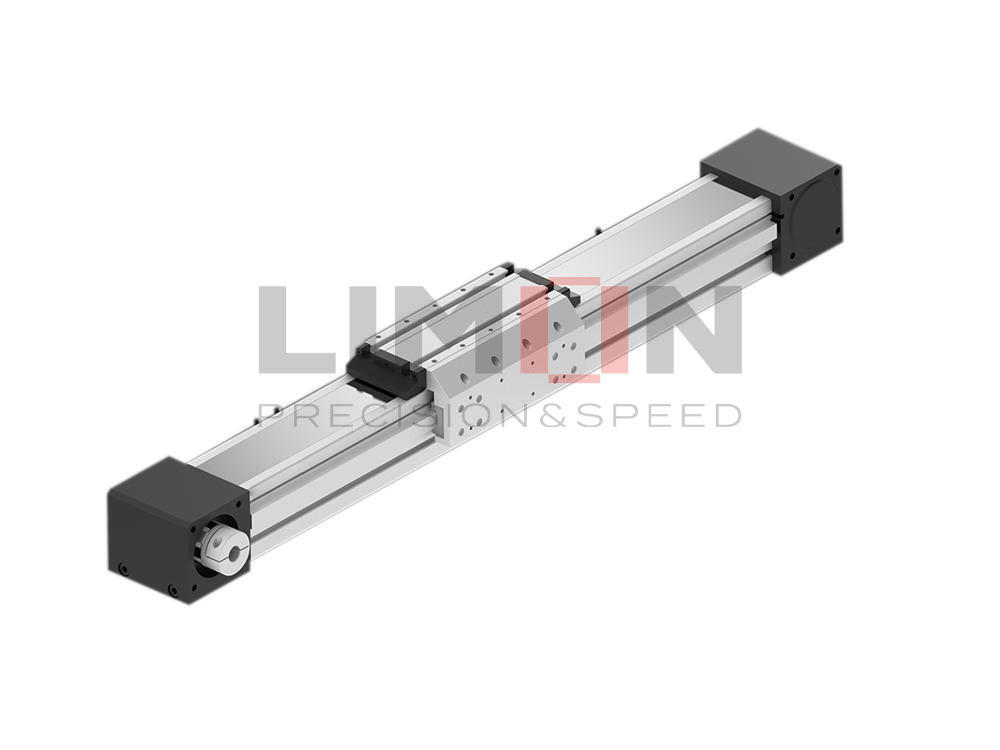
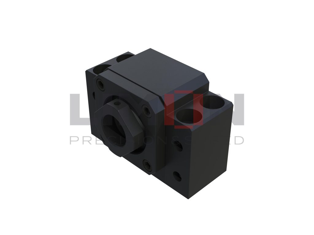
A ball screw typically converts rotary input into linear movement. A rotating screw shaft drives a ball nut along its axis, with recirculating balls reducing friction between the contacting surfaces. This design is widely used in precision positioning, CNC machinery, and industrial automation because it can provide high efficiency and repeatable movement.
Under suitable conditions, a ball screw can also be backdriven. An axial force applied to the nut may cause the screw shaft to rotate. This can be useful when the application requires linear input to produce rotary output, but the result depends on the screw lead, friction, preload, load conditions, and mechanical configuration. Engineers should verify backdriving performance rather than assume that every ball screw can perform this function reliably.
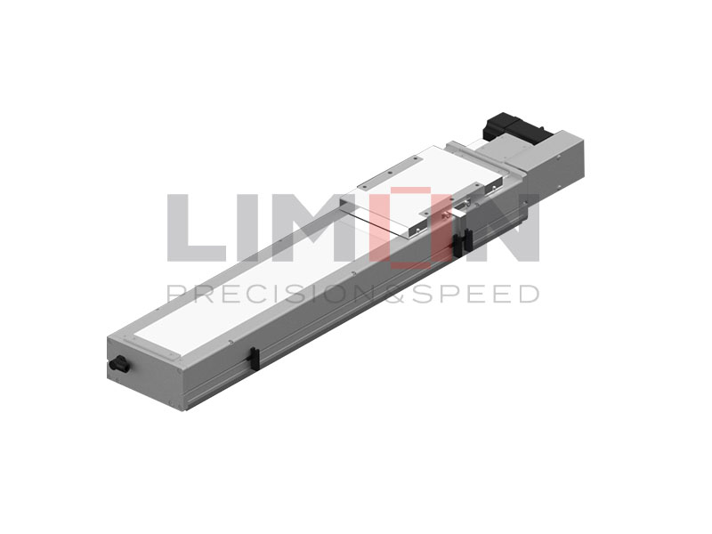
Linear actuators provide controlled straight-line movement and may be used to drive a separate conversion mechanism. For example, an actuator can push a rack connected to a pinion or move a linkage that rotates a component through a defined angle.
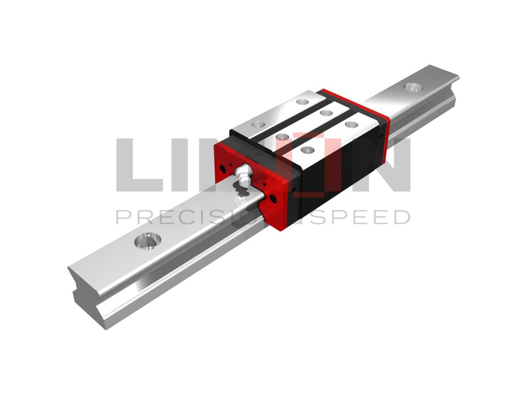
Linear guide rails help support moving loads and maintain the intended travel path, while linear bearings provide guidance in compatible shaft-based systems. These components do not independently create rotary output, but they can improve the stability of the linear input stage.
Limon offers these core linear motion products through its independent website. Our fully integrated production line supports manufacturing consistency, while direct communication with the manufacturer and technical assistance help customers match components to load, stroke, speed, accuracy, and installation requirements.
What Factors Should You Consider When Choosing a Motion Conversion Mechanism?
Choosing the right mechanism requires evaluating the complete motion profile rather than focusing only on whether linear movement can produce rotation. A design that works well for a lightweight positioning system may be unsuitable for a high-load industrial machine.
Consider the following factors before making a decision.
Required rotational angle and linear stroke: Determine how far the input component must travel and how much rotation the output must produce. Rack and pinion systems offer a predictable relationship between travel and angle, while crank and cam mechanisms can generate more complex motion profiles.
Torque and linear force: Establish the force available from the linear input and the torque required at the rotary output. Account for friction, mechanical losses, changing linkage geometry, and dynamic loads.
Speed and acceleration: Define both linear input speed and rotary output speed. Rapid acceleration can increase inertial loads, vibration, and wear, so the mechanism must be suitable for the actual duty cycle.
Accuracy and backlash: Precision applications may require low-backlash gearing, carefully controlled clearances, rigid mounting, and suitable feedback systems. Backlash can affect repeatability, especially when movement reverses direction.
Efficiency and backdriving: Evaluate friction and energy losses throughout the mechanism. If the system relies on axial force to rotate a screw, verify that the screw assembly can backdrive under the expected operating conditions.
Installation space and maintenance: Consider available space, mounting orientation, lubrication access, environmental conditions, and the ease of replacing components.
A practical comparison is shown below.
| Mechanism | Main advantage | Key consideration |
| Rack and pinion | Direct conversion with predictable rotation | Backlash, alignment, and gear wear |
| Crank and connecting rod | Effective for reciprocating cycles | Nonlinear force and velocity |
| Scotch yoke | Compact motion-conversion layout | Contact stress and changing mechanical advantage |
| Cam and follower | Customizable motion profile | Profile design and follower contact |
| Backdrivable ball screw | Potentially efficient, controlled motion | Backdriving depends on screw design and load |
Limon’s product range and technical support can help customers assess which linear motion components are appropriate for their application. Our direct-sales approach also makes it easier to communicate project requirements and obtain guidance without unnecessary distribution layers.
Where Is Linear-to-Rotary Motion Conversion Used in Industry?
The conversion of linear motion to rotary motion is used across many industries where a straight-line input must produce controlled angular movement. Understanding these applications can help engineers identify the most appropriate mechanism for their machines.
Industrial automation: Automated assembly equipment may use a linear actuator to push a rack and rotate a component into position. Properly selected guides and bearings help maintain alignment during repeated cycles.
Packaging machinery: Packaging systems often combine linear feeding, cutting, sealing, and indexing operations. Mechanical linkages or cam mechanisms can synchronize movement and create repeatable rotary actions at specific points in the production cycle.
Robotics and positioning equipment: Some robotic fixtures and handling systems use linear actuators to drive linkages that change the angular position of grippers, supports, or other mechanical elements. The conversion mechanism must be matched to the required angular range and payload.
Valves and industrial controls: A linear input can drive a linkage that rotates a valve stem or operating shaft. In these applications, required torque, operating angle, sealing requirements, and safety considerations are important.
Mechanical and reciprocating equipment: Crank mechanisms can transform the linear force of a piston into rotation, as seen in engines and other reciprocating machinery.
In each application, the conversion mechanism must be designed around actual operating conditions. Load variation, repeated acceleration, contamination, temperature, and mounting accuracy can all affect service life and performance.
Limon supports industrial motion-system development with linear guide rails, ball screws, linear bearings, and linear actuators. Our integrated production line provides control over manufacturing processes, while our focus on product quality and technical support helps customers build dependable systems. By purchasing directly from Limon, customers can communicate their requirements with the manufacturer and explore suitable solutions for their equipment.
Why Choose Limon for Reliable Linear Motion Solutions?
A reliable motion conversion system begins with the right mechanical design, but long-term performance also depends on the quality, compatibility, and consistency of its components. A poorly matched guide, screw, bearing, or actuator can introduce excess friction, misalignment, vibration, and premature wear.
Limon specializes in linear motion products, including linear guide rails, ball screws, linear bearings, and linear actuators. These components support a wide range of industrial applications where controlled movement, reliable operation, and consistent performance are essential.
Our fully integrated production line supports a coordinated manufacturing process and greater control over product consistency. Rather than focusing only on individual parts, we recognize that motion components must work together within the larger mechanical system.
Our direct-sales model allows customers to purchase through the Limon independent website and communicate their requirements directly with the manufacturer. This approach helps simplify product sourcing and makes it easier to discuss application-specific needs.
Product quality is equally important. Industrial motion components must be selected and manufactured to suit the required load, speed, accuracy, and operating environment. Proper component selection helps reduce unnecessary wear and supports stable machine performance.
Finally, Limon provides technical support to help customers evaluate their requirements and identify suitable linear motion products. Whether you are developing an automated machine, upgrading existing equipment, or sourcing components for a new industrial project, our team can help you consider stroke, load, speed, mounting, and system compatibility.
If your application involves converting linear movement into rotary output, start by defining the required motion and evaluating the mechanism best suited to your design. Limon is ready to support your project with reliable, high-performance linear motion solutions.
Conclusion: Build Better Motion Systems With Limon
Converting linear motion to rotational motion requires the right combination of mechanical geometry, force, torque, speed, and accuracy. Rack and pinion systems, crank mechanisms, Scotch yokes, cam systems, and backdrivable screw assemblies each offer distinct advantages for different applications.
By understanding these mechanisms and evaluating your operating requirements, you can make more informed design decisions and build a reliable motion system.
Limon combines a fully integrated production line, direct manufacturer sales, a broad linear motion product portfolio, and technical support to help customers find dependable industrial solutions.
Choose Limon for reliable, high-performance linear motion products engineered to support your application.