Put each rotating part into the inertia calculation, including the platter, adapters, fixtures and workpiece. Use their mass distribution about the output axis. A small part near the edge can contribute more inertia than a heavier piece near the center. For a part change, update the offset as well as the mass.
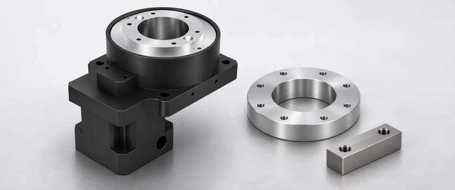
Build the total about the output axis
Use the same axis for every term. For a uniform solid disk centered on the axis, inertia is ½mR². For a uniform ring with inner radius r and outer radius R, it is ½m(R² + r²). For an offset part, find its inertia about a parallel axis through its center of mass, Jc, then add md², where d is the distance between the two axes. Use metres and kilograms to get kg·m². Oriental Motor's inertia calculation guide covers the common shapes and the relationship between output inertia and inertia referred to the motor.
Consider a horizontal table rotating about a vertical axis. The example treats each part as uniform. For a fixture with pockets, fasteners or uneven attachments, use its CAD mass properties with the material densities assigned.
| Rotating item | Model and inputs | Inertia at the output |
|---|---|---|
| Solid platter | 4.0 kg, radius 0.150 m | 0.04500 kg·m² |
| Centered annular adapter | 2.0 kg, inner radius 0.050 m, outer radius 0.100 m | 0.01250 kg·m² |
| Rectangular part | 1.5 kg, 0.080 × 0.060 m in plan, centered 0.130 m from axis | 0.02660 kg·m² |
| External load total | Sum of the three | 0.08410 kg·m² |
For the rectangular part, its center term is 1.5 × (0.080² + 0.060²) ÷ 12 = 0.00125 kg·m². The offset contributes another 0.02535 kg·m². Remember both terms when copying data from CAD. If it already reports inertia about the desired rotary axis, the offset is already included.
Relate that inertia to the move
Assume a 90° index in 0.50 s with equal acceleration and deceleration periods, no constant-speed segment and no settling allowance in the 0.50 s. Then acceleration magnitude is 4θ/t², about 25.13 rad/s². Peak output speed is about 60 rpm. The external load's acceleration torque is Jα ≈ 2.11 N·m at the output. Add the applicable friction, process torque and actuator inertia on a consistent basis. Use the actual motion profile if it has a cruise segment, unequal ramps or jerk limits.
If a reducer turns its motor ten revolutions per output revolution, the external load inertia referred to the motor is 0.08410 ÷ 10² = 0.000841 kg·m². The motor reaches about 600 rpm during the example move. Add the manufacturer's specified internal inertias on the shaft basis they use, and check the motor torque and speed limits with transmission losses accounted for. Verify permissible load inertia for the complete combination as well as the torque required throughout the cycle.
Repeat the check for the heaviest and widest setups
The heaviest tool isn't always the one with the largest inertia. List the alternate fixtures and the possible workpiece positions. Update the mass model with these positions before choosing a ratio or a shorter move time. Oversize platters and eccentric fixtures also create bearing loads. Use the separate axial, radial and moment load check for that part of selection.
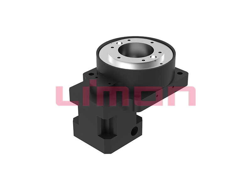
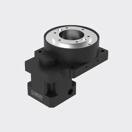
For a DYH series or other hollow rotary actuator enquiry, attach the fixture drawing or inertia about the intended axis, required angle, move profile, dwell, duty cycle and any external forces to the application request. Include the combinations for which the machine will need to run at full rate.