Improper mounting of a ball screw leads to misalignment, vibration, and mechanical failure. A proper method ensures accuracy, load balance, and long-term performance in motion systems.
The correct method for mounting the ball screw shaft involves secure installation on the base and table, accurate support alignment, motor connection, and routine maintenance to ensure long-term reliability.
Keep reading to learn the step-by-step approach for secure and precise ball screw shaft installation.
Installation onto the Table and the Base
The foundation of reliable ball screw performance lies in correctly mounting the screw shaft onto the machine base and table. The base provides fixed support, while the table carries the moving components. Accurate placement prevents deflection, preload variation, and dynamic vibration.
Key Steps:
-
Surface Preparation: Ensure the mounting surface is clean, flat, and deburred. Irregularities can introduce angular misalignment or excessive preload on the screw.
-
Fixing the Screw Shaft: Align the shaft along the designated linear path using dial gauges or laser alignment tools. It must remain straight with zero lateral deviation.
-
Positioning of Bearing Blocks: End support units (fixed and floating) must be securely fastened onto the machined flats or slots.
-
Use of Locating Pins or Sleeves: Precision dowel pins or keys ensure the repeatable positioning of the ball screw housing relative to the machine bed.
For long travel systems, intermediate supports may be used to minimize shaft deflection. Special attention should be given to the mounting torque of the brackets, ensuring no warping of the ball screw shaft during clamping.
An accurately mounted shaft provides the foundation for preload consistency, vibration-free operation, and precise axial movement.
Checking the Accuracy and Fully Fastening the Support Unit
After basic mounting, verifying the alignment and securing the support unit is critical. The support unit typically includes the bearing housing that holds the fixed or floating ends of the ball screw shaft. Poor alignment here can cause excessive torque, ball return jamming, or uneven preload.
Alignment Verification:
-
Dial Indicator Method: Use a dial gauge to check axial runout and lateral deviation across the shaft length.
-
Parallelism Check: Ensure the screw axis is parallel to the machine slideways or linear guides. Deviation causes cross-loading on the nut.
-
Concentricity Test: Verify that the center of the bearing housing aligns with the screw shaft center.
Fastening Tips:
-
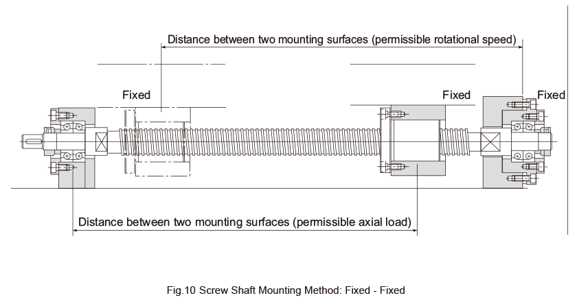
Fixed Side: Mount this side first. It supports both radial and axial loads. It is usually a combination of angular contact bearings in duplex or back-to-back arrangement.
-
Support Side (Floating): Allow for slight axial displacement due to thermal expansion. Typically uses deep groove or cylindrical bearings.
Torque values for bolts must follow manufacturer guidelines to avoid distortion. After fastening, rotate the shaft manually—any resistance or uneven feel indicates misalignment.
Proper fastening and alignment of the support unit enhance screw lifespan, minimize vibration, and maintain mechanical accuracy across the motion cycle.
Connection with the Motor
Connecting the ball screw to the driving motor is the next critical phase. The method depends on the machine layout, drive system, and motor type (stepper, servo, or AC synchronous).
Coupling Method:
-
Flexible Couplings: These absorb minor misalignments and reduce stress between the motor shaft and ball screw. Jaw, bellows, or Oldham couplings are common.
-
Rigid Couplings: Used where perfect alignment is guaranteed, often in short-drive systems with minimal shaft deflection.
Alignment Requirements:
-
The motor axis must be coaxial with the screw shaft to avoid axial thrust or vibration.
-
Check angular and radial misalignment tolerances (usually <0.02 mm).
Motor Mounting:
-
A flange mount or adapter bracket secures the motor housing.
-
Apply anti-vibration washers to reduce resonance at high speed.
Some advanced systems use a belt-driven setup or a gearbox between the motor and the screw for torque amplification or layout constraints. In all cases, the torque transmission must be backlash-free for precision control.
A well-aligned, securely coupled motor enhances the efficiency, repeatability, and control of the ball screw assembly.
Mounting Procedure and Maintenance
Mounting the ball screw shaft is not a one-time activity—it should be complemented by a repeatable procedure and periodic maintenance to preserve long-term performance.
Mounting Procedure:
-
Check Mounting Surfaces: Clean and measure with a dial gauge or optical comparator.
-
Install Fixed End First: Align the support bearing block and torque fasteners uniformly.
-
Place and Align the Shaft: Ensure axial runout is within tolerance.
-
Connect the Floating End: Secure without over-constraining thermal expansion.
-
Install Nut Housing or Bracket: Center-align with linear guide path.
-
Attach Motor Coupling: Align shafts, install coupling, and test rotation.
-
Lubrication: Apply correct lubricant (grease or oil) according to the specification.
-
Functional Test: Rotate manually and under low-power load. Listen for abnormal noise or observe non-linear movement.
Routine Maintenance:
-
Lubrication: Inspect every 500–1000 hours. Replace old grease or refill oil.
-
Preload Check: Monitor for loss of stiffness or increase in axial play.
-
Bearing Health: Inspect support bearings for temperature rise or vibration.
-
Alignment Audit: Perform semi-annual alignment verification using laser systems.
Ball Screw Mounting Summary Table
| Step | Key Operation | Inspection Items | Optimization Tips |
|---|---|---|---|
| Mounting to Base and Table | Clean surfaces, mount bearing blocks with locating pins | Surface flatness, shaft straightness, block position | Use laser alignment tools and control bolt torque |
| Align and Fix Support Units | Cross-tighten bolts, check axial and radial deviations | Running smoothness, verticality, axial fit | Use dial gauge to align; rotate manually to detect binding |
| Motor Connection | Use flexible or rigid couplings, ensure coaxial mounting | Coaxiality, fastener condition, no-load rotation | Flexible couplings compensate small misalignment; add vibration isolators |
| Procedure and Maintenance | Install step by step, perform function test, set maintenance schedule | Lubrication state, preload status, temperature and vibration | Log data trends; recheck axial clearance and alignment every 6 months |
Summary
Proper shaft installation, alignment, coupling, and maintenance of ball screws ensure precise, reliable motion performance in industrial applications.For further questions please contact [email protected]