An aluminum frame can carry profile linear rails if the mounting faces stay flat and aligned after the rails, carriage and payload are installed. The design decision is where to put the precision surfaces. They can be machined into the base or provided by separate mounting plates. A frame extrusion's nominal dimensions alone give you no acceptance result for either option.
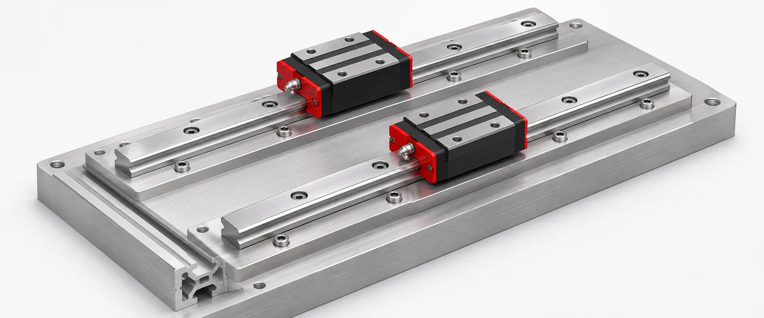
Choose a continuous seat for the rail
On a machined plate or bed, specify flatness along each rail seat and the height relationship between the seats. Put the master reference shoulder on the same drawing. Its relief should clear the rail corner radius so the rail can contact the horizontal and vertical surfaces together. LIMON's datum shoulder guide shows how to check that interface.
On an extrusion frame, a separate machined strip or plate can provide the rail seat and reference edge. Check how the strip bears on the frame, particularly at joints or where the fastening line crosses a cavity. A strip that bends between supports may pass a check near the bolts while the carriage pitches as it crosses the span. If you intend to machine the extrusion directly, specify how the frame will be supported during machining and inspection. Clamping a bowed profile flat during cutting can leave a different shape after it is released.
Design the threaded joint with the base material in mind
Before setting a tightening torque, check the rail manufacturer's requirements alongside the fastener size, alloy, available thread engagement and joint design. A shallow blind hole can bottom the screw before it clamps the rail. An extrusion slot with a sliding nut needs its own check for pullout, movement and local stiffness. HIWIN's guideway catalog lists different torque guidance by base material for its own rails. Confirm the torque and fastener details for the rail and aluminum joint on your drawing.
Long rails bring a second issue. Steel and aluminum grow by different amounts over the same temperature change. The assembly's response depends on how the rails and frame are restrained. For a long or temperature-sensitive axis, compare straightness and running resistance at the operating temperature as well as at assembly. Agree on the restraint arrangement before drilling a bed full of locating features.
Inspect the base in the state in which it will run
THK's rail mounting instructions show different master-rail methods depending on whether a physical reference shoulder exists. With two rails, establish the master before using it to align the second. The dual-rail parallelism measurement procedure gives indicator setups for checking the second rail over its travel.
| Assembly state | Readings to keep | What a change helps isolate |
|---|---|---|
| Base installed on its working supports | Each seat and the relative height between them | A twist or step already present in the bed |
| Rails seated and tightened | Master straightness and second-rail alignment | Shift or distortion introduced by seating and fastening |
| Table fitted without the working load | Full-stroke movement and resistance | A carriage interface that pulls the rails out of alignment |
| Representative payload fitted | Straightness at the work point and travel resistance | Deflection of the bed, mounting plate or carriage under load |
Use the same measurement reference when comparing stages. If the axis runs freely before the table is fitted and binds afterward, measure the table mounting faces before changing rail preload. If it changes mainly with payload position, check the bed and intermediate plate deflection under the moving load. The two symptoms lead to different repairs.
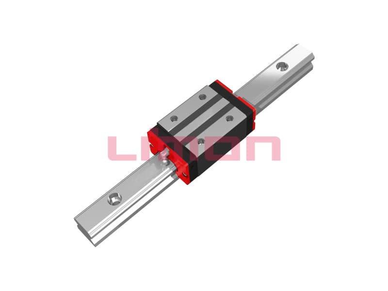
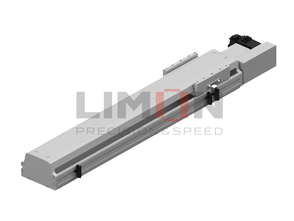
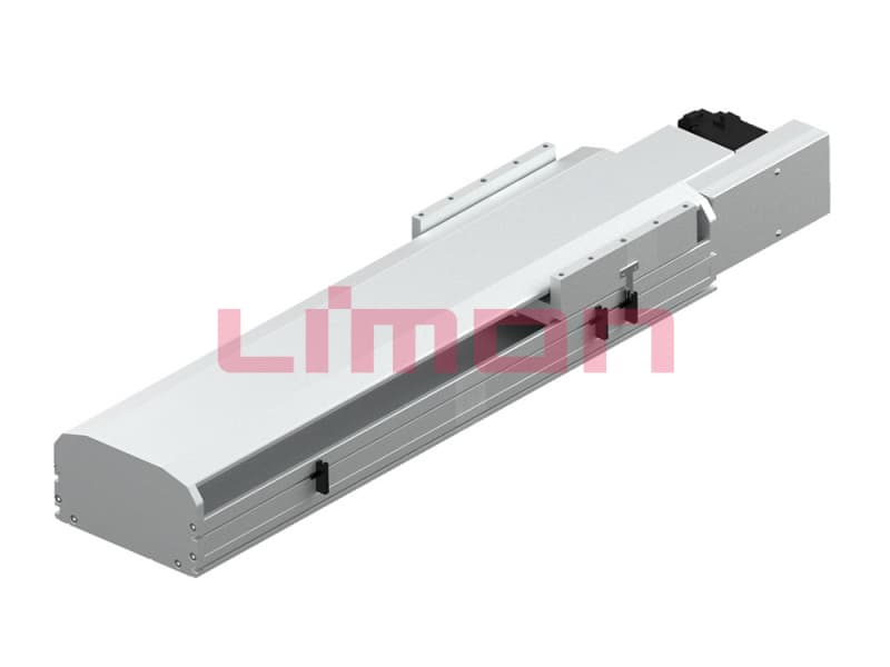
To review a mounting arrangement for LIMON H Series guideways, include a section through the extrusion and rail seat, the fastener details, rail spacing, mounting orientation and expected payload in the запрос о применении. Include the work point and its straightness requirement so the mounting checks can be tied to what the machine needs to do.