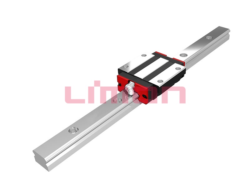
A linear guide datum shoulder locates the rail or carriage against a reference face. Its height, corner relief and stiffness must match the selected guide drawing. A shoulder that is too high can foul the moving block; an oversized corner radius can prevent the rail from seating even when the mounting bolts feel tight.
For an OEM machine builder, the useful question is whether the guide’s ground reference faces actually contact the intended machine datums after assembly. This guide covers that drawing and inspection task. Start with the chosen linear guideway series, rather than a generic shoulder dimension copied from another machine.
Identify the locating faces before dimensioning the base
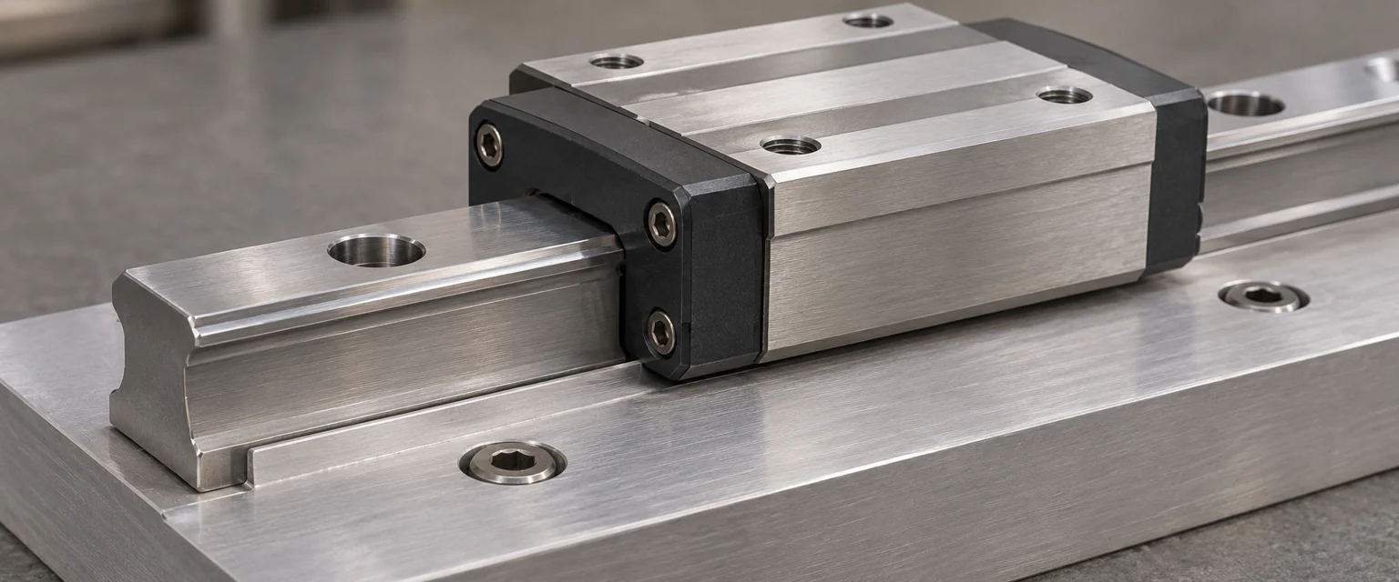
The bottom mounting face supports the rail vertically. The side datum controls its lateral location. The moving table has a corresponding mounting face and may have a locating shoulder for its reference carriage. These functions need separate drawing references.
Mark which rail establishes the machine reference and which rail will be aligned to it. Also identify the datum side of the actual rail and block. Logos, grease nipples and end caps are not reliable universal rules for recognizing that side across suppliers.
THK’s mounting-surface guidance explains that shoulder height, corner shape and perpendicularity affect reference-face contact. Its marking conventions belong to its products; obtain the corresponding convention for the LIMON series you order.
Four shoulder details to close on the drawing
| Drawing detail | What must be established | Failure the check is intended to prevent |
|---|---|---|
| Shoulder height | Permitted height for the chosen rail and carriage | Interference with a block, seal or chamfer |
| Corner relief | Maximum base radius or an approved relief groove | Rail resting on the corner instead of the mounting plane |
| Shoulder thickness | Enough local stiffness for the locating method | Shoulder bending under a lateral clamp |
| Perpendicularity | Relationship of side datum to mounting plane | Partial face contact and rail tilt |
Keep the rail-side and carriage-side values separate. A block’s lower corner and a rail’s lower corner need not have the same geometry. Check the full carriage envelope through the travel, including accessories such as wipers and lubrication fittings.
A corner relief is useful only if it clears the mating edge without removing the intended bearing area. Do not increase the relief until a poorly aligned rail appears to fit. Resolve the underlying dimensions first.
Check seating before applying final bolt torque
Clean the mounting plane and the locating face, then inspect for burrs around tapped holes and damaged edges. A rail can bridge a burr while appearing flush at its ends. Tightening it in that condition can distort the rail and obscure the original problem.
During a controlled trial assembly, establish whether the bottom face seats and whether the side reference face contacts the shoulder. Use the inspection method appropriate to the finish and tolerance: a clearance check, an indicator, or a controlled contact check. A visual inspection alone cannot establish a micron-level relationship.
Record the rail position before and after final tightening. If alignment changes, investigate seating, clamp force, hole position and local base deformation before treating the change as a rail defect. Bolt size and torque must come from the selected assembly specification.
A drawing-review example
Consider a base design using a shoulder dimension inherited from an older, larger guide. The new rail fits the mounting-hole pattern, but its carriage passes close to the shoulder. The correct review has three independent checks:
- Overlay the new carriage’s complete moving envelope on the base section.
- Compare the rail and block corner clearances with the proposed shoulder and relief.
- Check that the remaining shoulder section can take the intended lateral locating force.
Passing the first check does not prove the other two. This is a geometry-review example, not a recommended shoulder size for any particular LIMON model.
What belongs in the inspection record?
Use the same datum names on the drawing, machining inspection sheet and assembly sheet. Otherwise one supplier may inspect a hole pattern from the base edge while the assembler locates the rail from a different shoulder.
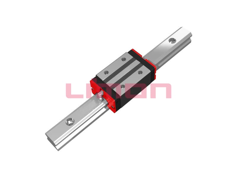
Record the guide model, reference side, shoulder height, corner condition, mounting-plane condition and the method used to confirm seating. Add the drawing revision and any measured change after tightening. If the machine will be built repeatedly, retain the accepted base-section drawing as part of the assembly specification.
For paired rails, shoulder design and rail parallelism measurement are different tasks. Correct locating surfaces help establish alignment; they do not remove the need to verify it.
Does every rail need a machined shoulder?
No. Guide systems can use other locating and securing methods. The method must suit the guide, base stiffness and operating loads. THK illustrates several guide securing arrangements; that range of arrangements is a reason to specify the method explicitly rather than assume every machine needs the same shoulder.
If there is no locating shoulder, identify how the rail will be aligned and how its position will be maintained. Mounting-bolt clearance is an assembly allowance, not a controlled lateral datum.
Send a section drawing with the guide enquiry
For a review of LIMON H Series guideways, provide the rail and block model, mounting orientation, base material, a section through the proposed shoulder, and the required travel accuracy. Include any wiper or lubrication clearance constraints. Contact LIMON with those details so the discussion can address the actual interfaces rather than nominal rail width alone.