Four blocks carrying an 800 N load do not necessarily see 200 N apiece. Move the load toward one corner of the table and the blocks nearest that corner take more of it. Acceleration can shift the distribution again, even when the payload stays bolted in place.
The calculation below estimates the vertical reactions on a horizontal stage with two rails and two blocks per rail. It gives you four loads to take into a catalog check. It assumes a stiff plate and base, identical blocks with equal vertical stiffness, and no appreciable assembly distortion.
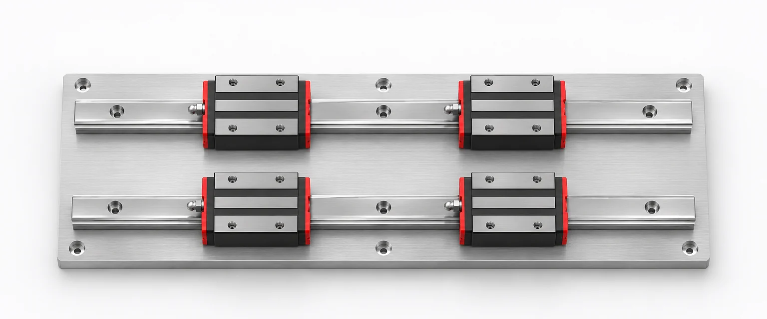
Put the load on the same drawing as the blocks
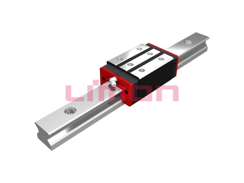
Draw the block centers first. Let X run along the rails, Y across the rails and Z upward. The two blocks on each rail are spaced a apart along X. The rail centerlines are b apart along Y. Measure both dimensions center to center. A rail's overall length tells you little about the pitch leverage if its two blocks sit close together.
An offset downward load creates pitch about Y and roll about X. A sideways force applied away from the center can also create yaw about Z. Yaw calls for a lateral load calculation. The vertical reaction calculation below leaves that component separate. THK's guide block loading examples distinguish loads by direction and mounting layout.
Work through the four corners
Suppose the total downward load W is 800 N. Its line of action is 60 mm forward and 40 mm to the right of the center of the four blocks. The block spacing a is 0.32 m and rail spacing b is 0.24 m. In this example, front and right are the sides that gain load.
- The centered share is 800 ÷ 4 = 200 N per block.
- The pitch moment is 800 × 0.060 = 48 N·m. It adds 48 ÷ (2 × 0.32) = 75 N to each front block and removes 75 N from each rear block.
- The roll moment is 800 × 0.040 = 32 N·m. It adds 32 ÷ (2 × 0.24) ≈ 66.7 N to each right block and removes that amount from each left block.
The factor of two appears because two blocks share each end or side of the couple. For another layout, keep the signs tied to the free-body sketch. Changing the offset to the opposite side changes which blocks gain load.
Now consider an acceleration phase in which a 160 N inertial force along X acts 0.10 m above the drive force line. Assume the lines share the same Y coordinate so this pair adds no yaw. In the direction that increases the front load, the added pitch moment is 16 N·m and the total pitch moment is 64 N·m. The front or rear adjustment becomes 100 N per block.
| Bloc | Constant-speed vertical load | Vertical load in that acceleration phase |
|---|---|---|
| Front right | 341.7 N | 366.7 N |
| Front left | 208.3 N | 233.3 N |
| Rear right | 191.7 N | 166.7 N |
| Rear left | 58.3 N | 33.3 N |
Both columns sum to 800 N. The higher front-right reaction comes from redistribution, even though the total vertical force stays the same. Reverse the acceleration moment in the calculation for deceleration. Where the process force changes along the move, calculate that phase separately too.
Use spacing to test a layout change
With the same 64 N·m pitch moment, increasing the block spacing from 0.32 m to 0.40 m reduces the pitch contribution from 100 N to 80 N per block. The front-right estimate drops to 346.7 N. Wider rail spacing would reduce the roll contribution instead. Check what those changes do to travel, carriage length and mounting access before committing either change to the drawing.
An algebraic reaction below zero means the block would have to transmit load in the reverse vertical direction in this model. Check the selected guide's rating in that direction and the rail, block and fastener arrangement. If the bed or carriage bends enough to change the load sharing, replace the equal-stiffness estimate with a model that represents the actual structure.
Take two sets of numbers into selection
Keep the largest directional and combined load at each block for the static check. Keep the loads and travel distances for the working portions of the cycle for the life check. The relevant combination factors and ratings come from the selected guide, not from the four-block arithmetic. THK's selection sequence treats equivalent load, static safety and nominal life as separate steps. LIMON's guide load capacity article covers the rating terms used in those checks.
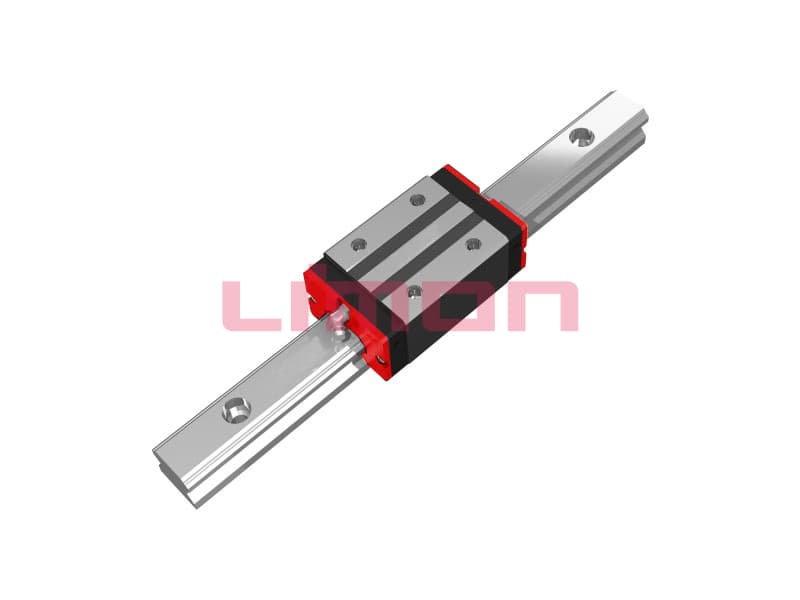
If you are comparing sizes of Guidages linéaires LIMON, send the plan view, both center spacings, load offsets, drive height and acceleration profile with your application enquiry. Include any process forces with their point of application so they can be assigned to the right blocks and directions.