Is your mechanism wasting force, creating backlash, or failing early because linear travel is being converted into rotation the wrong way?
Linear to rotary motion conversion uses a rack and pinion, crank, screw, belt, cable drum, or ratchet to transform straight-line force and travel into angular displacement and torque. The right mechanism depends on whether motion is continuous or reciprocating, plus the required speed, torque, efficiency, precision, stroke, and duty cycle.
Below, compare the mechanisms, calculations, applications, design risks, and technologies shaping future motion systems.
What Is Linear to Rotary Motion Conversion?
Linear motion moves an object along a straight path, while rotary motion turns an object around an axis. A conversion mechanism transfers the force, speed, and travel of a linear input into the torque, angular speed, and rotation required by an output shaft.
The input may be continuous, such as a moving rack or belt, or reciprocating, such as a piston moving repeatedly between two endpoints. The output may make unlimited full rotations, rotate through a limited angle, or advance in controlled steps.
The conversion does not create energy. It exchanges force for speed or travel according to the mechanism’s geometry. A design that produces greater output torque generally requires more input force, a longer linear stroke, or a lower rotational speed.
Efficiency also matters. Friction in gears, bearings, seals, screw threads, and sliding joints reduces the mechanical power available at the output.
The basic power relationship is:
Linear power = Linear force × Linear velocity
For the rotating output:
Rotary power = Torque × Angular velocity
After allowing for mechanical efficiency:
Output rotary power = Input linear power × Efficiency
A successful system must therefore provide the required rotation without excessive friction, backlash, vibration, heat, or wear. The drive mechanism, linear guides, bearings, shaft supports, lubrication, and machine structure must be evaluated as one system.
Which Mechanisms Convert Linear Motion into Rotation?
The best mechanism depends on the input motion and the desired output. A rack and pinion is ideal for continuous linear travel, while a crank is better suited to repeated back-and-forth movement. A ratchet converts repeated strokes into one-directional steps, and a backdrivable screw can produce precise rotation from controlled linear displacement.
| Mécanisme | Input motion | Rotary output | Principaux avantages | Key considerations |
|---|---|---|---|---|
| Crémaillère et pignon | Continuous or reversing linear travel | Continuous or reversing rotation | Direct, compact, responsive, and suitable for long travel | Backlash, tooth wear, lubrication, and alignment |
| Slider-crank | Reciprocating linear movement | Continuous or oscillating rotation | Robust and widely proven | Dead-center positions and changing torque |
| Scotch yoke | Reciprocating linear movement | Rotary or oscillating movement | Compact with simple sinusoidal motion | Sliding friction and wear |
| Ball screw or lead screw | Axial movement of the nut or screw | Controlled screw rotation | High mechanical resolution and compact design | Backdrivability, lead, preload, and support bearings |
| Belt and pulley | Continuous linear belt movement | Continuous pulley rotation | Quiet, fast, and suitable for longer distances | Belt stretch, tension, and lower torsional rigidity |
| Cable and drum | Linear cable movement | Limited or continuous drum rotation | Simple routing and compact packaging | Cable layering, fatigue, and changing drum radius |
| Ratchet and pawl | Repeated linear strokes | Intermittent one-way rotation | Simple indexing and holding | Impact, noise, wear, and limited smoothness |
Rack-and-pinion systems provide a direct relationship between linear displacement and pinion rotation. They are well suited to steering mechanisms, gates, handling equipment, and long-stroke machinery.
Slider-crank mechanisms are common in engines, pumps, compressors, presses, and energy-harvesting equipment. However, output torque changes throughout each revolution and approaches zero at the dead-center positions.
Ball screws are particularly valuable when linear displacement must produce accurate, efficient rotary positioning. Not every screw is equally backdrivable, so thread geometry, lead, friction, preload, and load direction must be evaluated carefully.
How Do You Select the Right Conversion Method?
Begin by defining the motion itself. Ask whether the input travels continuously in one direction, reverses repeatedly, or completes a short stroke before returning. Then determine whether the rotary output needs continuous rotation, limited-angle movement, or step-by-step indexing.
For continuous linear input and continuous rotation, rack-and-pinion, belt-and-pulley, or cable-drum mechanisms are usually practical. A rack and pinion offers high rigidity and a direct mechanical relationship. A belt drive provides smoother and quieter operation when some compliance is acceptable.
For reciprocating input and continuous rotation, a crank mechanism is a natural choice. A flywheel may be needed to carry the system through dead-center positions and smooth the changing angular velocity. Multiple cranks or cylinders can also reduce torque fluctuation.
For intermittent one-directional rotation, a ratchet and pawl can convert every forward stroke into an angular step while preventing reverse rotation during the return stroke. If quiet operation and accurate indexing are required, an overrunning clutch or controlled servo mechanism may be more suitable.
A screw-based system is useful when a short, controlled linear displacement must create precise angular movement. A larger screw lead produces more rotation for the same linear travel but changes the force, torque, resolution, and backdriving characteristics.
Selection should also account for:
- Required output torque and rotational speed
- Available linear force and stroke
- Précision et répétabilité du positionnement
- Acceptable backlash
- Direction changes
- Duty cycle and operating life
- Noise and vibration limits
- Espace d'installation
- Environmental contamination
- Maintenance access
- Safety and holding requirements
The right mechanism is the one that meets the full operating profile—not simply the one with the highest rated force.
How Do You Calculate Rotation, Speed, and Torque?
Early calculations help determine whether a concept is practical before detailed component selection begins.
For a rack-and-pinion system, linear travel and angular displacement are related by the pinion’s pitch radius:
Angular displacement = Linear travel ÷ Pinion pitch radius
When angular displacement is expressed in radians:
θ = s ÷ r
Où ?
- θ is angular displacement
- s is rack travel
- r is the pinion pitch radius
Output torque can be estimated as:
Torque = Linear force × Pinion pitch radius × Efficiency
A larger pinion produces more torque from the same input force but requires more linear travel for each revolution. A smaller pinion turns more times over the same travel but produces less torque.
Rotational speed can be estimated from rack velocity:
Rotational speed = Linear velocity ÷ Pinion circumference
For a crank mechanism, the piston stroke is approximately twice the crank radius:
Stroke = 2 × Crank radius
This relationship is simple, but instantaneous torque is not constant. Crank angle, connecting-rod length, inertia, and load profile must be included in a detailed analysis.
For a screw mechanism:
Number of screw rotations = Linear travel ÷ Screw lead
A 5 mm lead produces one revolution for every 5 mm of axial travel. This relationship makes screw systems useful for accurate motion conversion, but the force needed to backdrive the screw depends heavily on efficiency and thread geometry.
Real designs must also account for acceleration, inertia, impact, bearing friction, preload, structural deflection, and a suitable safety factor. Average values alone may hide the peak force or torque that determines component size.
How Do Linear Guides and Bearings Improve System Reliability?
A conversion mechanism should transmit force, not compensate for an uncontrolled payload. Linear guides and bearings keep the input movement aligned, while rotary bearings support the output shaft and maintain correct engagement between moving components.
In a rack-and-pinion system, poor rack alignment can concentrate load on one edge of the gear teeth. This increases noise, backlash, surface stress, and wear. A stable linear guide arrangement keeps the rack moving along its intended path and helps maintain consistent gear engagement.
In a screw-driven system, misalignment between the nut, screw shaft, and support bearings can increase friction and create uneven internal loading. The result may be higher drive force, heat generation, vibration, positioning error, or premature fatigue.
A slider-crank mechanism also creates lateral force on its translating member. Suitable guides are needed to prevent that side force from damaging the actuator, piston, or connecting structure.
Engineers should evaluate:
- Linear guide spacing
- Bearing load direction
- Pitch, yaw, and roll moments
- Output-shaft support
- Gear or pulley alignment
- Rigidité structurelle
- Lubrification
- Protection contre la contamination
- Thermal expansion
- Backlash and preload
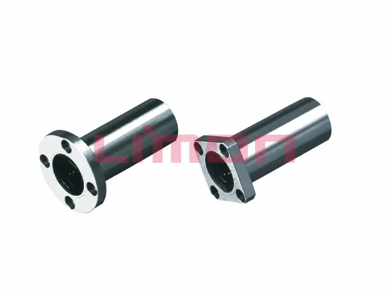
Linear bearings can provide an economical solution for moderate loads and straightforward travel. Profiled linear guides are better suited to applications requiring high rigidity, compact size, and resistance to moment loads.
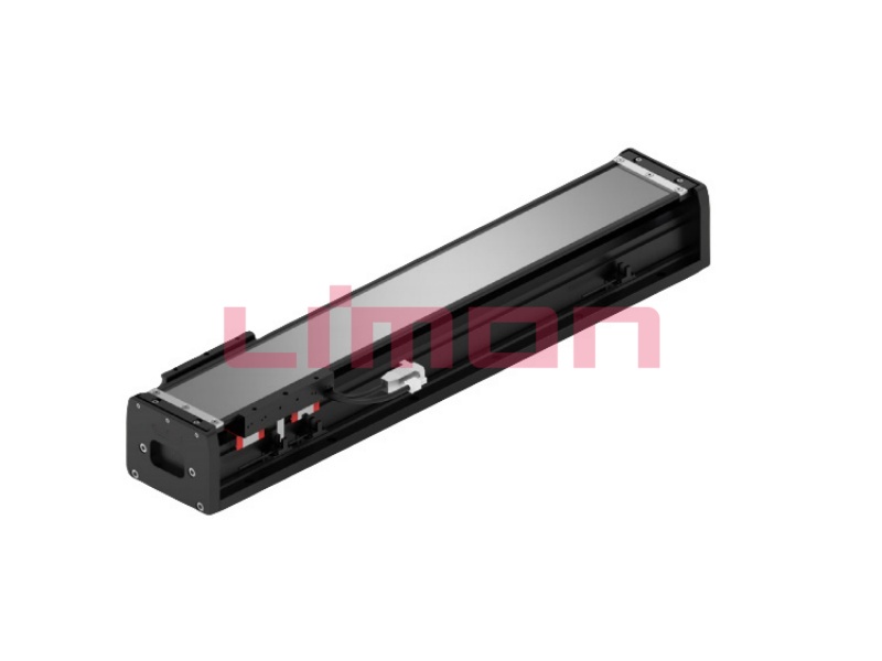
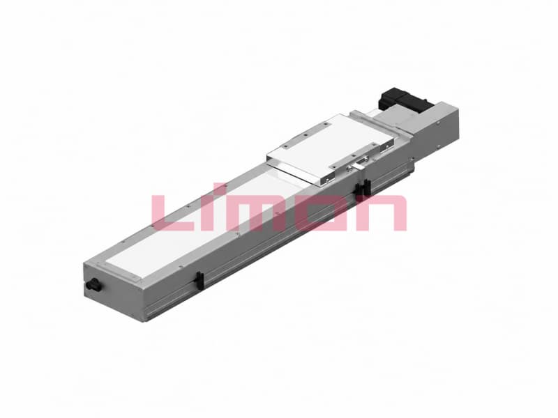
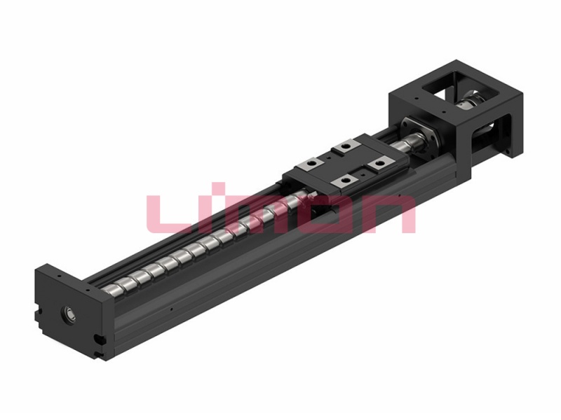
Limon supplies linear guides, linear bearings, ball screws, and linear actuators, allowing customers to coordinate the conversion mechanism with its supporting motion components instead of treating them as unrelated parts.
What Design Mistakes Should You Avoid?
One of the most common mistakes is choosing a mechanism without considering how torque changes throughout the operating cycle. A crank may provide sufficient average torque but stall close to dead center. A rack-and-pinion system may meet the nominal load while experiencing damaging impact during rapid direction changes.
Backlash is another frequent problem. Clearance between gear teeth, screw threads, joints, and bearings can create lost motion when direction reverses. Backlash may be acceptable in a manual adjustment system but unacceptable in automated inspection, dispensing, or precision positioning equipment.
Other avoidable problems include:
- Using the screw, rack, or actuator as the only load guide
- Applying significant side loads to a linear actuator
- Selecting bearings from static load alone
- Ignoring shock and emergency-stop forces
- Operating beyond the screw’s critical speed
- Allowing a compression-loaded screw or rod to buckle
- Using insufficient shaft support
- Installing gears or pulleys with poor alignment
- Applying excessive preload
- Providing inadequate lubrication
- Ignoring thermal expansion
- Leaving cables or sensors exposed to moving parts
Overrunning loads also require attention. A descending load, moving vehicle, flywheel, or high-inertia mechanism can drive the system faster than intended. Brakes, torque limiters, clutches, counterbalances, or regenerative controls may be needed.
Finally, do not assume that a high-efficiency system will hold position after power is removed. Efficient ball screws and low-friction drivetrains may backdrive readily. The machine must include an appropriate load-holding and safety strategy.
How Will Future Technology Improve Linear-to-Rotary Systems?
Future systems will combine better mechanical efficiency with more sensing, control, and operational intelligence. The objective is not simply to create rotation, but to control torque, speed, position, energy use, and equipment condition throughout the machine’s life.
Smart motion systems can monitor force, motor current, temperature, vibration, travel, speed, and completed cycles. Changes in these signals may reveal increasing friction, poor lubrication, misalignment, gear wear, or bearing damage before the machine stops unexpectedly.
Energy recovery is another important development. In applications with reciprocating loads, descending masses, or repeated acceleration and braking, part of the mechanical energy may be captured, stored, or returned to the electrical system. Efficient screws, bearings, and guides improve the value of this approach by reducing energy lost through friction.
Additional developments include:
- Low-backlash gear and screw designs
- Higher-efficiency ball screws
- Compact integrated motion modules
- Lightweight components with high rigidity
- Quieter recirculation and gear engagement
- Digital motion simulation
- Condition-based maintenance
- Network-connected sensors and controllers
- Application-specific seals, coatings, and lubrication
- Modular systems that shorten installation time
These technologies will not eliminate the need for good mechanical design. Accurate alignment, correct bearing support, suitable guidance, and realistic load calculations remain essential.
Limon’s integrated production line, product range, and technical support capabilities allow us to respond to this shift toward efficient, connected, and application-specific linear motion systems.
Conclusion
Réussi conversion d'un mouvement linéaire en mouvement rotatif begins with a clear understanding of the input stroke, output rotation, force, torque, speed, accuracy, and duty cycle. Rack-and-pinion systems suit direct continuous conversion, cranks handle reciprocating motion, ratchets create indexed rotation, and screw mechanisms offer compact, precise control.
System reliability also depends on suitable linear guides, bearings, shaft supports, alignment, lubrication, and safety measures. With integrated manufacturing, dependable quality, direct sales, and professional technical support, Limon provides reliable, high-performance linear motion solutions for industrial applications.
Ready to Develop a More Reliable Motion System?
Rendez-vous sur le site web indépendant de Limon pour découvrir nos guides linéaires, nos vis à billes, nos roulements linéaires et nos actionneurs linéaires.
Send the Limon technical team your input force, stroke, speed, output torque, rotation range, duty cycle, installation space, and operating environment. We will help you evaluate the application and select compatible linear motion components for a reliable, efficient system.