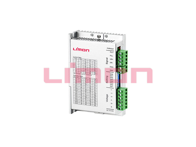
Before setting the top speed on a pulse-commanded servo axis, calculate how many input pulses the drive needs per second. The result depends on the configured command pulses per motor revolution and how far the machine travels in that revolution. A fast motor and screw won't deliver the requested feed if the controller's pulse output reaches its limit first.
Translate the configured command pulses into millimetres
Let P be drive command pulses per motor revolution after electronic gearing. Let L be screw lead in mm per screw revolution, and i the number of motor revolutions per screw revolution. Then each command pulse represents L ÷ (i × P) mm of nominal travel. At a requested linear speed v in mm/s, the required pulse rate is f = v × i × P ÷ L in Hz.
Check how the drive manual defines the electronic gear setting. One drive may let you enter input pulses per revolution. Another relates a command unit to internal feedback increments through a ratio. The encoder's resolution helps define the drive's feedback. It doesn't by itself establish the number of external pulses needed to command one revolution. For a belt axis, substitute the pulley travel per revolution and use the motor-to-pulley ratio. The LIMON lead comparison explains how screw lead changes the travel side of that calculation.
Compare speed and scaling before choosing a setting
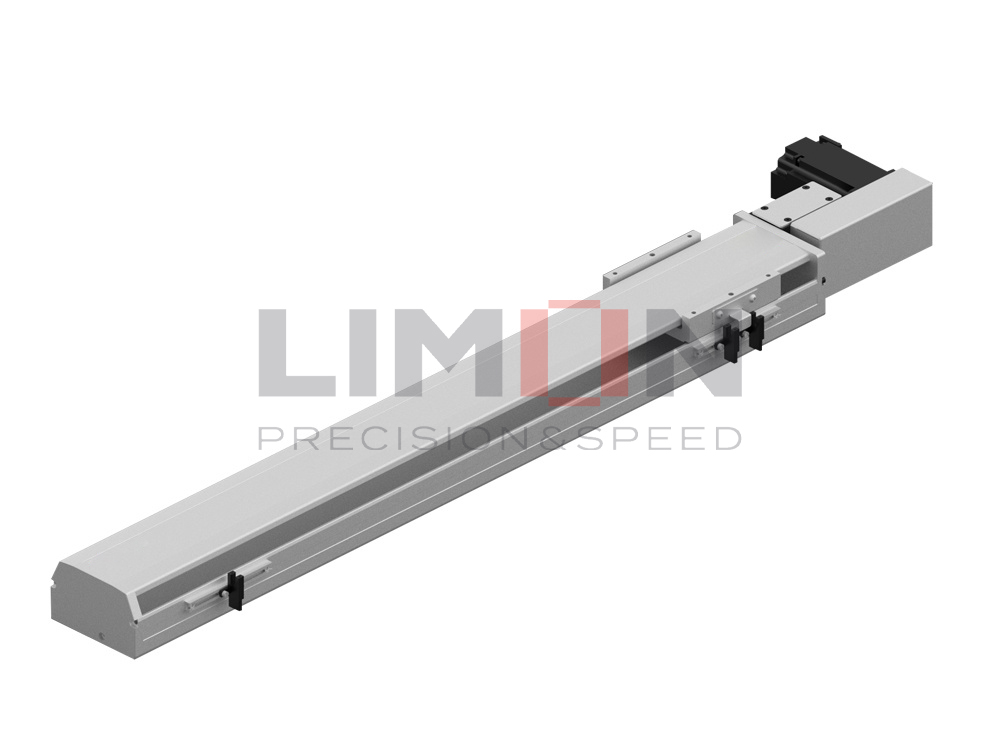
Suppose a direct-coupled 5 mm lead screw needs to move at 250 mm/s. That takes 50 revolutions per second, or 3,000 rpm. Assume the selected controller and drive input arrangement permit up to 200 kHz for this example.
| Command scale | Required at 250 mm/s | Nominal travel for one pulse | Speed at the assumed 200 kHz ceiling |
|---|---|---|---|
| 10,000 pulses per motor revolution | 500 kHz | 0.5 µm | 100 mm/s |
| 3,000 pulses per motor revolution | 150 kHz | About 1.67 µm | About 333 mm/s |
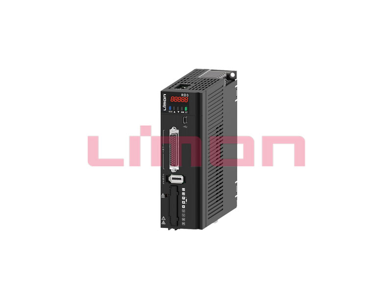
The second scale fits the assumed interface at the requested speed. Before using it, check that its command increment suits how the machine is programmed. The drive still needs to support the selected ratio, and the screw, supports and motor still need to handle the operating speed and loads. Neither table row is an LD3-LP input specification or a statement of actual positioning accuracy.
Check both ends of the signal path
Use the lower frequency limit of the controller output and drive input for the selected signal mode and electrical connection. In pulse/direction mode, frequency normally refers to one train of motion pulses, with direction conveyed separately. Other formats count edges differently. Also check the minimum high and low times and the timing of a direction change. Schneider Electric's Lexium 32M manual illustrates how input format and timing are specified. The numerical limits must come from the actual drive and controller documentation.
During commissioning, confirm direction and actual displacement using a short commanded move under the approved setup. With the second scale above, 30,000 command pulses should represent 50 mm of nominal travel. A consistent scale error leads back to the electronic gear ratio, lead or pulse convention. Errors that appear only at higher rates warrant checking the allowed timing, electrical interface and command and feedback traces before changing the ratio again. Follow the device manual for wiring and shielding.

Pour un LIMON LD3-LP pulse-type drive enquiry, include the controller model, output mode, desired feed and increment, mechanical ratio and screw lead. Use the page de contact de l'application to request the input limits and parameter instructions for the proposed combination. The catalog library lists documents by drive family.