A frequency reading is useful only with its measurement span and belt specification. The same belt at the same tension can read 30 Hz in one position and 37.5 Hz in another if the free span changes from 500 mm to 400 mm. For a linear actuator, use the maker's specified carriage position, measurement span and target before making any adjustment.
Write down the setup before taking a reading
Find the axis model, stroke and belt part number. The service instructions should identify where the carriage belongs and which free belt span to measure. Check whether the maker gives a frequency range directly or specifies static span tension. If the procedure calls for a tension calculation, look up the mass per metre of the installed belt width. A per-width mass value needs to be multiplied by the belt width once.
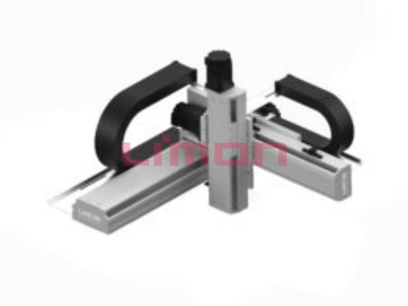
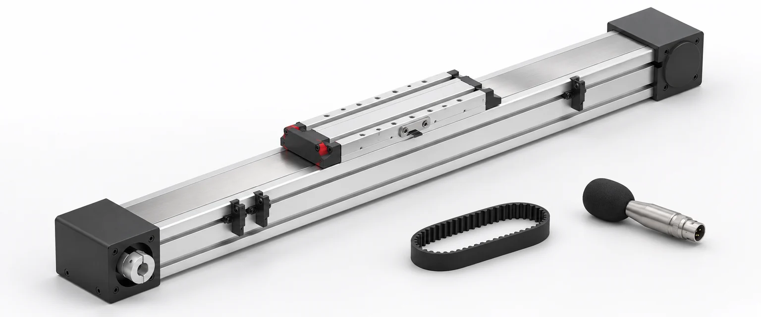
The span is the unsupported length that can vibrate between its effective boundaries. On a linear module, a carriage clamp or other contact point can shorten that length. Measuring the extrusion, or copying a pulley center distance from a drawing, can give the wrong input. If access depends on disassembly, follow the manufacturer's maintenance procedure for that enclosure. The ITC80 catalog page shows a closed belt axis, which illustrates why a photograph of the assembled module cannot tell you where to take the reading.
What a frequency measurement tells you
The string approximation gives T = 4 × μ × L² × f²où T is static span tension in newtons, μ is belt mass per metre in kg/m, L is the vibrating span in metres and f is the fundamental frequency in hertz. Gates' sonic tension meter manual gives the equivalent form for its meter's inputs and discusses the effect of belt bending stiffness. That stiffness can make a simple frequency conversion less reliable on some short or stiff spans.
Consider a hypothetical belt with μ = 0.12 kg/m. At 30 Hz on a 0.50 m span, the estimate is 108 N. Here is what changes if the span or frequency changes.
| Measured span | Frequency | Estimated tension with the same belt |
|---|---|---|
| 0.50 m | 30 Hz | 108 N |
| 0.40 m | 37.5 Hz | 108 N |
| 0.40 m | 30 Hz | 69 N, rounded |
The third row explains why carrying over a frequency without its span can lead to a low setting. These values belong to the example and are not service settings for a LIMON axis.
Measure, adjust and check the locked setting
Use the approved stopped condition for service. With the carriage at the specified reference position and the correct span accessible, place the meter as its manual directs and excite the belt gently. Take several readings before using the result. A number that jumps between widely separated values is a reason to check the span, sensor placement and surrounding vibration. Avoid averaging readings that come from different vibration modes.
If the model's procedure permits adjustment, use its specified method, then repeat the measurement after the adjuster is locked. Record the carriage position and final readings. Low tension can reduce resistance to tooth jump during acceleration. Increasing tension also increases load on the pulley bearings, so an extra turn on an adjuster is a poor substitute for the correct target.
Restore the covers before running the axis. Verify the move under the expected payload and check position after repeated reversals. If it still misses position at the correct tension, investigate the drive, the belt clamp and the mechanics before adjusting again. LIMON's bidirectional repeatability test gives a way to separate readings by approach direction.
For an existing LIMON belt driven axis, send its model, stroke, serial or order reference, carriage position and measured span with your service enquiry. Ask for the procedure and target that correspond to that configuration.