Is your conversion system losing torque, accuracy, and service life because the mechanism was selected before the load was fully understood?
Linear motion is converted into rotation using a rack and pinion, crank, lever, cable drum, ratchet, or backdriven screw. The best mechanism depends on whether the output must be continuous, oscillating, or indexed, as well as the required torque, angle, speed, precision, reversibility, and safety.
This guide compares conversion methods, calculations, applications, selection criteria, failure risks, and future design trends.
What Does Linear-to-Rotary Motion Conversion Involve?
Linear to rotary motion conversion transforms straight-line force and displacement into torque and angular movement around a shaft. The input can come from an electric linear actuator, pneumatic cylinder, hydraulic cylinder, moving carriage, spring, counterweight, or manually operated mechanism.
Before selecting a mechanism, engineers should answer four questions:
- Must the shaft rotate continuously, oscillate, move through a limited angle, or index in steps?
- How much output torque is required throughout the complete movement?
- How much linear stroke is available?
- Can the mechanism be backdriven, or must it hold position when power is removed?
These questions matter because different mechanisms produce very different output behavior. A rack and pinion provides a direct, nearly constant relationship between rack travel and shaft angle. A crank produces changing torque throughout each revolution. A lever is simple but normally limited to partial rotation. A backdriven ball screw provides precise multi-turn rotation but may require a brake.
The correct solution must also account for efficiency, backlash, acceleration, bearing loads, alignment, lubrication, structural rigidity, and foreseeable overloads.
Which Conversion Mechanism Is Best for Your Application?
The following comparison provides a practical starting point:
| Mechanism | Typical output | Primary advantage | Main design concern |
|---|---|---|---|
| Crémaillère et pignon | Continuous or limited rotation | Direct force-to-torque relationship | Backlash and tooth loading |
| Slider-crank | Continuous or oscillating rotation | Handles repeated reciprocating motion | Dead-center positions |
| Lever and shaft | Limited-angle rotation | Simple and economical | Nonlinear torque |
| Backdriven ball screw | Precise multi-turn rotation | High efficiency and predictable ratio | Uncontrolled backdriving |
| Cable and drum | Continuous or limited rotation | Flexible routing | Cable stretch and changing radius |
| Chain and sprocket | Continuous or limited rotation | Positive engagement | Wear, noise, and tension |
| Ratchet and pawl | Intermittent one-way rotation | Simple indexing | Impact and discrete movement |
A rack and pinion is often the strongest general-purpose choice when the input travels along a fixed straight path and the output must rotate predictably. A slider-crank is suitable for repetitive machines in which continuous shaft rotation is produced from reciprocating input. A lever works well for valves, dampers, clamps, and other limited-angle mechanisms.
Backdriven ball screws are especially relevant when high axial force, precise rotation, compact geometry, or energy recovery is required. However, the best mechanism is determined by the complete motion profile—not by whichever option appears mechanically simplest.
How Do You Calculate the Required Geometry and Torque?
For a rack and pinion, the basic relationship between linear travel and pinion rotation is:
\[ x=r\theta \]
Où ?
- \(x\) is rack travel in meters;
- \(r\) is pinion pitch radius in meters;
- \(\theta\) is shaft rotation in radians.
Approximate output torque is:
\[ T=F r \eta \]
Where \(F\) is input force and \(\eta\) is mechanical efficiency.
Consider a system with 100 mm of available linear travel that must rotate a shaft through 90 degrees. Because 90 degrees equals 1.571 radians:
\[ r=\frac{0.100}{1.571}=0.0637\text{ m} \]
The required pinion pitch radius is approximately 63.7 mm. If the actuator supplies 1,200 N and estimated efficiency is 90%:
\[ T=1200\times0.0637\times0.90=68.8\text{ N·m} \]
This is the approximate available torque before applying allowances for acceleration, gear-tooth loading, friction variation, impact, and service factor.
Static torque alone is not enough. The mechanism must accelerate the pinion, shaft, attached tooling, and external load within the available time. Engineers should calculate peak torque, continuous torque, angular acceleration, cycle frequency, and emergency-stop loading before finalizing component size.
When Should You Use a Backdriven Ball Screw?
A ball screw normally converts motor rotation into linear travel, but its low-friction rolling contact makes reverse operation possible. When an axial force moves the ball nut relative to the screw, the helical raceways cause the screw or nut to rotate. This is known as backdriving.
Approximate backdrive torque can be estimated with:
\[ T_b=\frac{F P \eta}{2\pi} \]
Où ?
- \(T_b\) is backdrive torque;
- \(F\) is axial input force;
- \(P\) is screw lead;
- \(\eta\) is ball screw efficiency.
For a 1,000 N input force, 10 mm lead, and 90% efficiency:
\[ T_b=\frac{1000\times0.010\times0.90}{2\pi}=1.43\text{ N·m} \]
If the linear input speed is 200 mm/s, the 10 mm lead produces:
\[ \frac{200}{10}=20\text{ revolutions per second}=1,200\text{ rpm} \]
This example illustrates the ball screw’s mechanical relationship: high axial force can generate controlled multi-turn rotation at relatively modest torque.
Backdriven ball screws can be useful in testing equipment, energy-recovery systems, counterbalanced axes, and mechanisms requiring a precise relationship between linear travel and rotation. Because ball screws are normally backdrivable, vertical or safety-related systems may require a brake, counterbalance, or redundant holding device.
How Should You Match the Mechanism to the Application?
Begin with the required output rather than the available components. Specify whether rotation must be continuous, reversible, oscillating, limited-angle, or intermittent. Then document output torque, angular travel, rotational speed, acceleration, repeatability, cycle rate, duty cycle, and holding requirements.
Next, define the linear input:
- Available force and stroke;
- Maximum and average speed;
- Acceleration and deceleration;
- Mounting direction;
- Positioning accuracy;
- Available installation envelope;
- Expected operating life.
Choose a rack and pinion for direct bidirectional conversion and relatively constant geometry. Choose a slider-crank for continuous rotation from repetitive reciprocation, provided dead-center behavior is addressed. Use a lever for simple limited-angle rotation. Select a ratchet for one-way indexing. Consider a backdriven ball screw for efficient, precise multi-turn output.
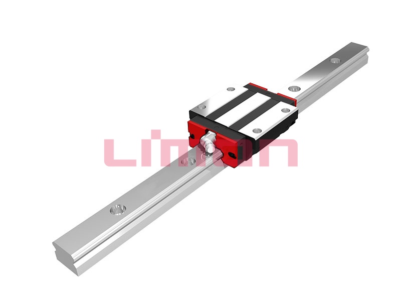
The linear input must also be guided correctly. An actuator rod or ball screw should not be expected to support large side loads or overturning moments. Linear guides and bearings should carry these external loads while the actuator or screw transmits axial force.
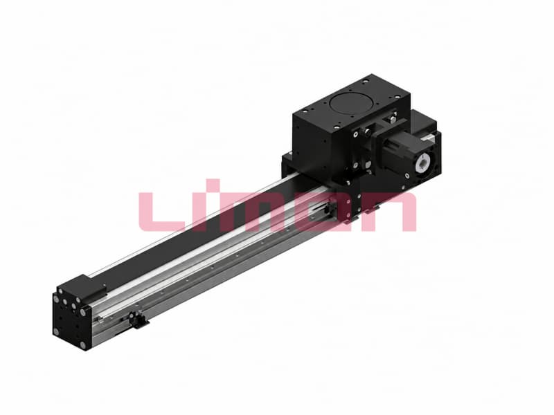
Limon can help customers coordinate the ball screw, linear guide, bearing arrangement, and actuator so the complete mechanism operates as a unified system.
What Design Errors Cause Conversion Systems to Fail?
Backlash is one of the most common problems. Clearance between gear teeth, screw and nut raceways, pins, joints, or bearings creates lost motion when direction reverses. Preloaded gears, suitable ball screw preload, correctly fitted bearings, and rigid mounting structures can reduce this error.
Misalignment creates another major risk. If an actuator pushes a rack, lever, or crank at an unintended angle, the resulting side force can damage the actuator, nut, bearings, or linear guide. Mounting datums must control parallelism, perpendicularity, and shaft position.
Other frequent errors include:
- Calculating static torque but ignoring acceleration;
- Selecting components from peak ratings without checking duty cycle;
- Ignoring crank dead-center positions;
- Allowing a vertical ball screw to backdrive without a brake;
- Using an undersized shaft or bearing arrangement;
- Failing to protect gears and screws from contamination;
- Applying excessive preload, which increases friction and heat;
- Operating beyond ball screw critical speed;
- Ignoring emergency-stop and shock loads.
A dependable design should be evaluated across its entire movement, not only at its most favorable position. Testing should confirm torque, temperature, vibration, backlash, stopping behavior, and service life under representative operating conditions.
How Will Future Conversion Systems Improve Performance?
Future systems will combine precision mechanical components with sensing, software, and energy management. Encoders can monitor output angle, while force, torque, current, temperature, and vibration sensors can reveal wear, obstruction, lubrication failure, or increasing backlash.
Reversible ball screw systems may play a larger role in regenerative applications. When a load descends or decelerates, its linear energy can backdrive the screw and rotate a motor-generator. Compatible power electronics can then return part of that energy to a shared DC bus or storage system.
Simulation tools will also improve selection. Engineers will be able to compare mechanism geometry, inertia, stress, efficiency, and thermal behavior before producing a physical prototype. However, software cannot compensate for inconsistent raceways, inaccurate screw lead, weak guidance, or poor assembly.
Limon’s fully integrated production line gives us control over ball screws, linear guides, linear bearings, and linear actuators. This enables coordinated attention to screw geometry, preload, straightness, guidance, mounting interfaces, and assembly quality. Through direct sales, customers can also discuss special dimensions and application requirements directly with our technical team.
Conclusion :
Effective linear-to-rotary motion conversion begins with the required output—not a preferred mechanism. Rack-and-pinion, crank, lever, ratchet, cable, and backdriven ball screw systems each solve different motion challenges. Limon provides reliable, high-performance linear motion products supported by integrated manufacturing, consistent quality, direct sales, and application-focused technical support.
Designing a linear-to-rotary conversion system? Visit the Limon independent website to explore our ball screws, linear guides, linear bearings, and linear actuators. Send our technical team your input force, stroke, speed, output torque, rotation angle, duty cycle, mounting arrangement, and operating environment to discuss product selection or a customized solution.