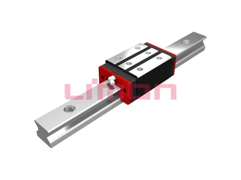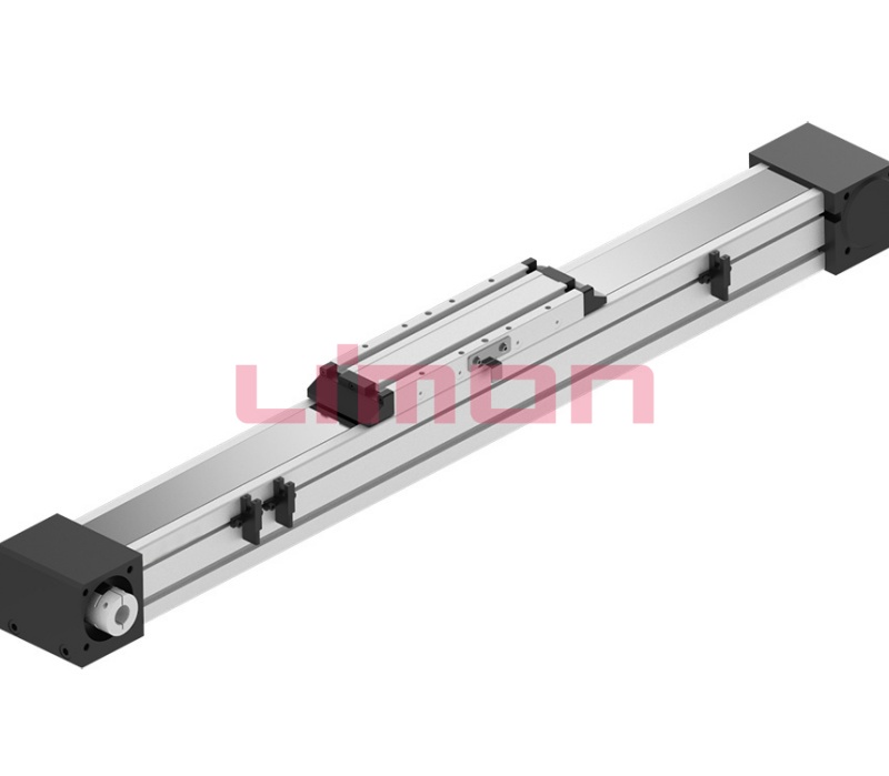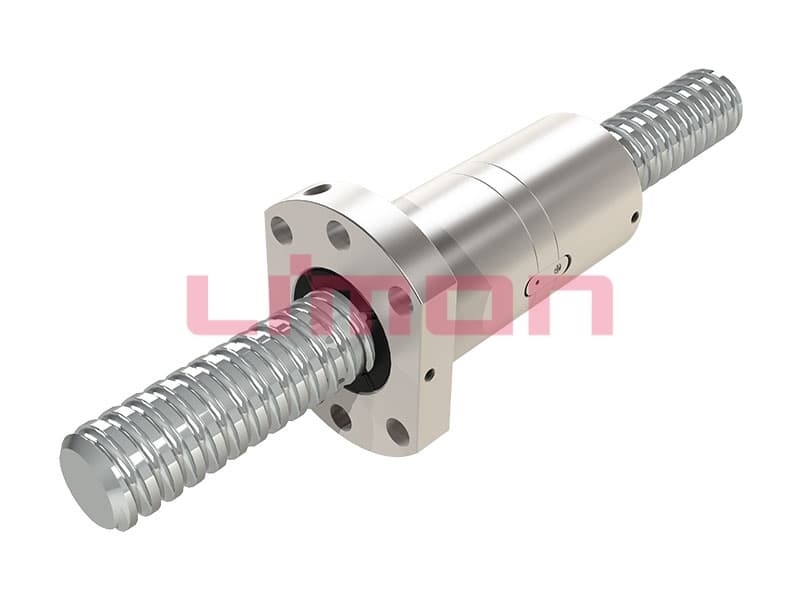
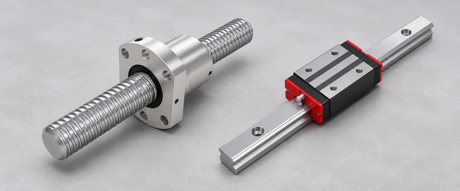
If a table travels freely on its guides but develops a tight spot when the ball nut housing is fastened, start with the alignment between the nut and the guided carriage. A ball screw assembly is sized for thrust along the screw. The guide system carries the lateral loads and moments. A small offset or angular error at the nut mount can turn the two systems into competing guides.
Follow the force through the carriage
The guide blocks should restrain the table against side force and tilt. The nut mount should transmit drive force along the shaft centerline. If the mounting face or pilot bore moves the nut off that line as its bolts are tightened, the screw has to bend or the nut contacts must react the extra force. The effect can vary with travel because the distance from the nut to each support changes.
Check both the offset of the nut bore and the angle of its mounting face. A housing can be centered at one station while its axis points across the screw line. Likewise, a coupling can accommodate a small error within its own limits and still leave a misaligned bearing housing elsewhere on the axis. Thomson's ball screw installation guide covers aligning the screw with the supports, guide and load.
Find the assembly step that introduced the drag
Use the approved stopped and supported condition for inspection. If the assembly procedure permits independent movement, compare the guided carriage and the supported screw separately before comparing the assembled axis. Keep the support condition, lubricant and measuring method consistent. Record positions along the travel and the shaft angle when a repeating peak appears.
| What you observe | Check before adjusting |
|---|---|
| Drag is present with the guides alone | Rail parallelism, table mounting surfaces, seals and cable drag |
| The supported screw has a repeating torque peak without the carriage connected | Shaft runout, bearings and coupling alignment |
| Drag rises after the nut flange bolts are tightened | Pilot diameter, mounting face squareness and the lateral position of the nut housing |
| The axis runs well unloaded and tightens under the working payload | Table deflection, support stiffness and whether the nut mount moves with load |
These comparisons identify which interface to measure. They are not a substitute for the manufacturer's permitted torque or alignment values. A motor current trace from a commissioned axis can help locate a problem, provided comparisons use the same direction, speed and payload. Current includes all the loads the motor sees, so it cannot identify a side load at the nut by itself.
Bring the nut to the guided line of travel
Establish the guides and table path first. Inspect the screw support seats and the nut housing against that path with the machine's assembly references. If the design provides adjustment at one support or at the nut mount, use the specified sequence to bring the components into alignment before final tightening. Use the approved fit and shimming method if an interface is out of position. Drawing the flange into place with its bolts can temporarily close a gap while leaving the screw bent.
Recheck the full usable stroke once the fasteners are at their specified condition. Include both ends and mid-travel. If the assembly will operate with an offset tool or load, compare the relevant measurements after the payload is installed. An unloaded axis that feels smooth can still be pushed sideways in service.
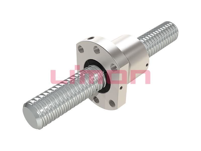
For a review of a LIMON ball screw assembly, include the nut flange dimensions, the screw support drawing, the guide layout and where the change in drag first appeared. Use the application contact page to send the sketch and the before-and-after readings. If the shaft has already worn, mark the affected travel region on the drawing.