A move can finish in the controller while the tool is still vibrating. For a camera, dispenser or probe, the usable cycle time ends when the work point stays inside the process tolerance long enough for the operation to begin. Measure that interval with the actual fixture and payload before comparing motion profiles.
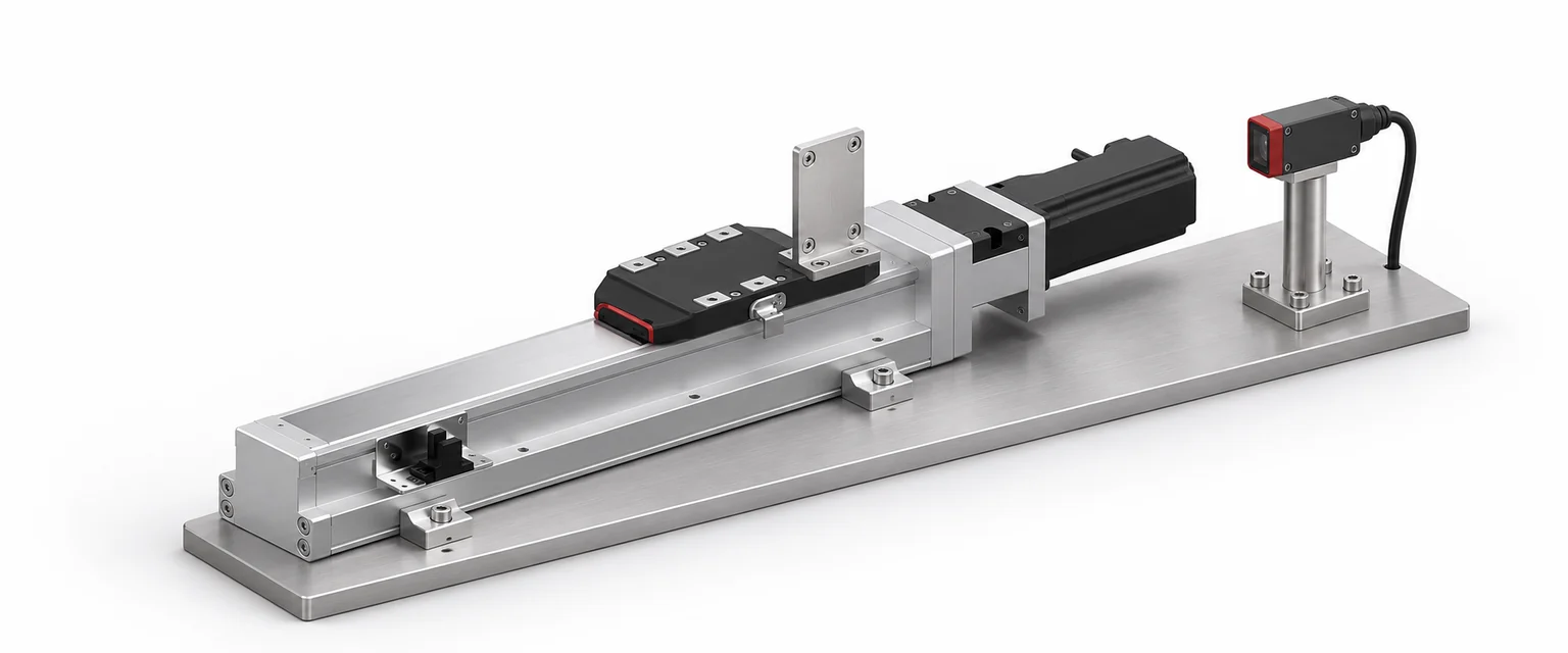
Put the command and the work point on one time trace
Record the command position, the feedback position and the signal that releases the next operation. Where carriage motion or tool deflection matters, measure the work point against a stable external reference. An encoder on the motor reports motor position. It cannot directly see flex in a bracket or motion between the tool and carriage.
Define a position band from the process requirement and agree on the time the work point must remain inside it. A controller can have a different in-position window or rely on a different sensor. For example, Beckhoff's position monitoring documentation describes monitoring entry to a specified window after the commanded position reaches its target. For machine acceptance, document the work-point band and the required hold time separately from the drive's signal.
For the timing convention below, start the settling clock at the end of commanded motion. Find the first instant from then at which the measurement enters the band and remains there for the full hold period. If it is already in band when the command stops and stays there, the wait is zero. If it leaves early, restart the hold clock. Record the end of the hold period as the earliest process-ready time for this test. If the signal that starts the process arrives later, keep that delay as a separate line in the cycle budget.
A slower move can finish the job sooner
Suppose an inspection head moves 60 mm, then must stay within ±20 µm for 20 ms before the camera may trigger. Compare two illustrative traces with identical payload, travel and tolerance.
| Time component | Profile A | Profile B |
|---|---|---|
| Move command to end of commanded motion | 110 ms | 125 ms |
| Wait until the start of the qualifying in-band period | 65 ms | 25 ms |
| Required hold in band | 20 ms | 20 ms |
| Earliest camera trigger after move start | 195 ms | 170 ms |
Profile B spends 15 ms longer moving and saves 40 ms of settling delay. It reaches the camera's release condition 25 ms earlier. The figures are a timing example, not measured performance of a LIMON module. The controller and the sensor also need enough time resolution to capture any brief excursions outside the band.
Use repeat runs to choose what to change
Test the move at the stations, loads and directions that matter to production. Keep the end position, velocity profile, jerk setting and payload in the record. A short move under a heavy cantilevered fixture may behave differently from a longer move with the same axis and a centered load.
If the work-point trace rings after the command stops, compare the same move with a gentler acceleration or jerk profile where the controller permits it. If the drive shows a stable stop and the external trace still moves, check the fixture and its support before trying to tune the motor around it. If traces settle consistently but the process starts late, measure the PLC, trigger and sensor delays separately.
For acceptance, retain the traces as well as the numbers. The LIMON repeatability procedure covers repeated final positions from each approach direction. Settling time adds the elapsed time before those positions are ready for use.
При сравнении линейные оси, send the move distance, payload and fixture drawing, required work-point band, hold period and cycle budget with your запрос о применении. Include an existing trace if you are replacing a module and need to match the timing of the rest of the machine.