Test bidirectional repeatability by repeatedly approaching the same target positions from both directions under controlled load, speed and temperature conditions. Report the spread within each approach direction and the difference between directions separately. A motor encoder count or command increment is not an independent measurement of carriage position.
For OEM acceptance, define the method before agreeing to a single “±” figure. Different reporting conventions can produce different numbers from the same readings.
Separate accuracy, repeatability and reversal behavior
Positioning accuracy describes the relationship between actual and commanded position over the specified range. Repeatability describes the consistency of repeated positioning under defined conditions. A direction-dependent offset can coexist with a small same-direction spread.
The distinction is visible in THK’s KR accuracy definitions, which define separate positioning repeatability, accuracy, running-parallelism and backlash checks. Its repeatability example uses a stated same-direction procedure. Do not relabel a same-direction catalog figure as a bidirectional machine result.
For the test below, keep the two approach directions as separate data groups. This is an engineering comparison procedure, not a claim of conformity to ISO 230-2 or another acceptance standard. If a standard is contractual, specify its edition and follow the complete method and reporting definitions.
Define the test contract
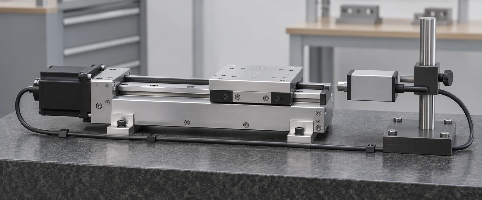
Agree on the module configuration, payload and its center of gravity, travel positions, velocity and acceleration, warm-up condition, dwell time, feedback arrangement and instrument. Specify whether the test measures the carriage, mounted fixture or actual tool point.
Choose measuring equipment with suitable resolution and uncertainty for the requirement. Keep its measurement axis aligned with the intended displacement and consider fixture movement and Abbe offset. An indicator mounted far from the relevant reference can respond to angular motion as well as translation.
Record ambient and module temperature conditions. A changing thermal state can create a drift across the sequence that looks like poor repeatability when readings from different times are pooled.
A repeatable acquisition sequence
- Assemble the module on its specified support and apply the agreed payload.
- Complete the agreed warm-up and establish the position reference.
- Select positions near the useful travel ends and within the working region, clear of end-stop conditions.
- Approach each target from one direction, dwell consistently and record the external position reading.
- Repeat the approach enough times for the agreed test, then collect the opposite-direction group under the same conditions.
- Repeat for each target, retaining timestamps and raw readings.
The approach distance must allow the programmed move to establish the intended motion state. Returning only a tiny distance may fail to reproduce the reversal behavior seen in production. Avoid changing the dwell or motion profile halfway through a comparison.
Worked example: repeatable from each side, different between sides
These six readings per direction are invented for calculation practice. Values are position errors in micrometres at a single target, not measurements of a LIMON axis.
| Запускайте | Positive-direction approach, µm | Negative-direction approach, µm |
|---|---|---|
| 1 | 1 | 5 |
| 2 | 2 | 6 |
| 3 | 1 | 5 |
| 4 | 0 | 4 |
| 5 | 2 | 6 |
| 6 | 0 | 4 |
The positive group has a mean of 1 µm and a range of 2 µm. The negative group has a mean of 5 µm and the same 2 µm range. The difference between the directional means is 4 µm. Pooling all readings produces a 6 µm range.
Reporting only a 2 µm range hides the reversal offset. Reporting only the pooled range loses information about the two individually consistent groups. Keep all three observations and label the convention. Do not convert a range to an unexplained “± accuracy” value.
Diagnose the pattern before changing compensation
If the two directional groups are separated but tight, investigate reversal-related mechanics and the feedback path. If both groups scatter, investigate settling, vibration, measurement stability and control behavior. If the group mean drifts with time, review thermal conditions and sequence timing.
These patterns help choose the next test; they are not one-to-one fault diagnoses. A motor-side encoder cannot independently reveal every displacement between the motor and the tool. Adding compensation before separating mechanical and measurement effects can hide the underlying issue.
For an axis using a screw drive, a separate nut and support movement check may help identify a mechanical contribution. Do not replace the positioning test with that static check: the two answer different questions.
What belongs in the acceptance report?
Include the tested module and motor configuration, payload, support arrangement, instrument and calibration status, measuring location, targets, approach distances, cycle parameters, dwell, temperature condition and raw data. Report each target separately and identify the worst result under the agreed convention.
State whether any correction or compensation was enabled. Keep the test program and drawing revision with the data so the same method can be repeated after installation or on later OEM builds.
Для LIMON linear module, including a candidate GSC-series axis, provide the payload and actual tool-point requirement. Agree the acceptance method with LIMON before comparing repeatability figures from different machines or suppliers.