If you specify a tighter guide seal for a dusty machine, allow for its resistance in the next motor calculation. The seal lip moves along the rail whenever the block moves. On an axis with several blocks, the extra drag can be noticeable during slow feed or after a long stop, even if the payload has stayed the same.
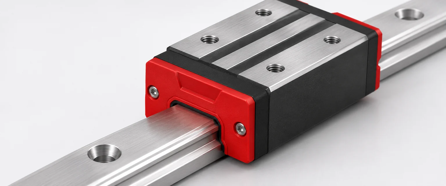
Read the seal option as part of the block specification
An end seal can contact the rail profile to keep contamination away from the raceways. A separate metal scraper can protect the seal by intercepting larger debris. Some scrapers run with a clearance while the lip carries the contact. The exact arrangement depends on the guide family. HIWIN's guideway catalog lists seal alternatives with different displacement resistance and distinguishes them from scraper options.
Ask for the resistance of the actual configuration and whether the supplier reports it for a seal, one block or a complete set. Check what the value includes. Adding the published drag for one block and then adding its seals again would count the same resistance twice if the number already includes them.
Measure startup and running resistance separately
For a horizontal axis, record the peak at breakaway and the force once motion is steady at a specified speed. Repeat in both directions with the same preload, lubricant, payload, temperature and dwell. A cold start and a freshly cycled, warm block can produce different readings. Describe both conditions if the machine must start after an overnight stop.
A force reading at the carriage can include cable drag, rolling resistance and alignment effects. A sharp peak at one location warrants a check of the rail and brackets before treating it as seal drag. When comparing seal options, use matched blocks and a consistent setup. The general LIMON guide load article explains the role of guide loading. The resistance comparison here belongs in the drive calculation.
| Observation | Next measurement |
|---|---|
| Higher peak after a long dwell across the same stroke | Compare cold and warm starts with the same lubricant and dwell |
| Higher force over the whole stroke with a different seal option | Compare steady force at matching speeds and confirm the exact seal codes |
| One tight spot repeats at the same travel position | Inspect rail seating and alignment around that position |
| Drag changes noticeably with cable position | Record the cable carrier condition separately from the block comparison |
Convert added drag at the carriage to shaft torque
Suppose a comparison under matched conditions shows 2 N more steady resistance per block. Four blocks add 8 N. A direct screw drive with a 10 mm lead and an assumed efficiency of 0.90 needs about 0.014 N·m more torque to overcome that resistance. The calculation is 8 × 0.010 ÷ (2π × 0.90). This example applies to the screw shaft while moving in the driving condition. For startup, use the breakaway force and the applicable drive data. For a belt axis, refer the measured resistance to the pulley pitch radius and account for any transmission losses.
Use the resulting torque in the matching operating points of the cycle. A small increase in steady torque can matter on a machine that runs continuously. The starting peak can matter on an intermittent feed with a smaller motor. Oriental Motor's sizing relationships give the force-to-torque conversions for common drive mechanisms.
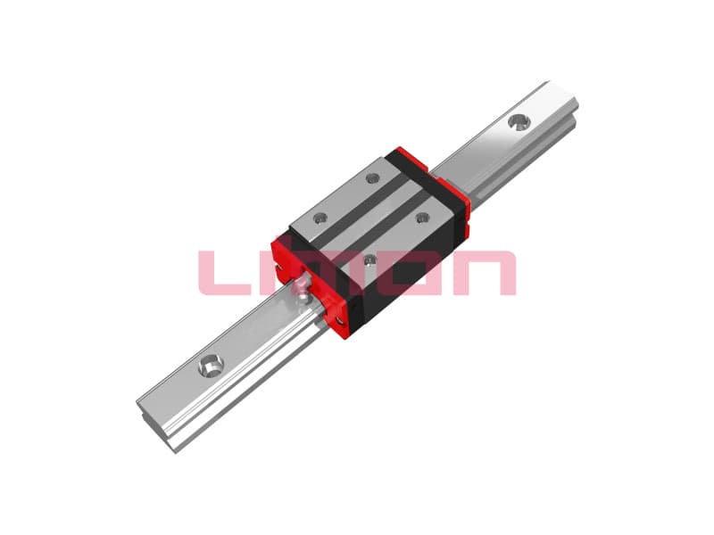
При заказе LIMON profile guideways, identify the block model and seal arrangement along with the contamination, lubricant, temperature and speed. Include your measured force or allowable drag in the enquiry so the seal choice can be checked against the motor budget.