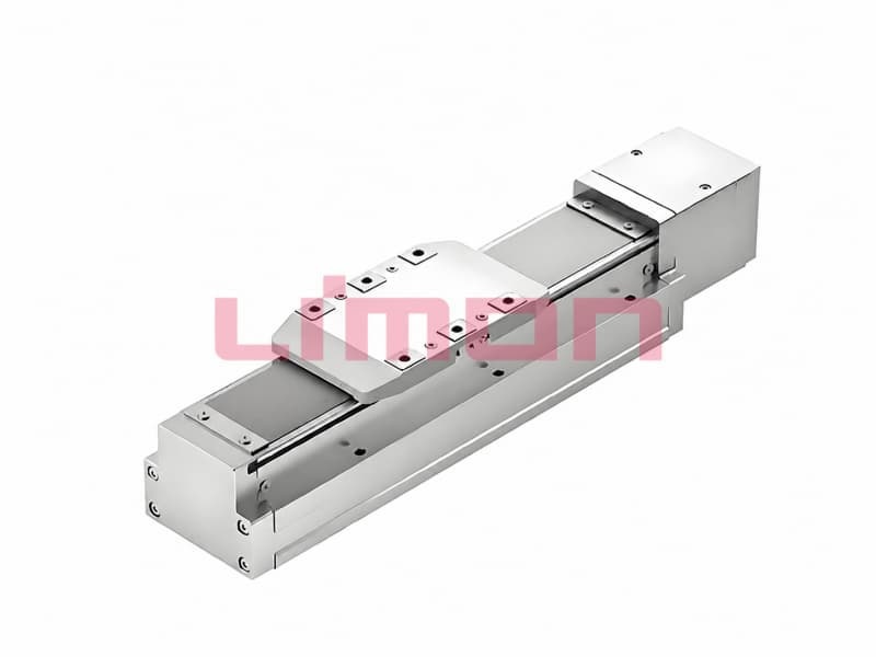
Effective stroke is the travel available for the intended task. Overall length is the physical envelope of the selected module and its specified accessories. A 400 mm required move therefore does not imply a 400 mm-long module. Carriage length, end structures, drive hardware and operating clearances occupy additional space.
This article addresses guided, rodless industrial linear modules, where a carriage travels along a fixed body. Rod-style actuators use different envelope relationships and should not be substituted into the same length calculation.
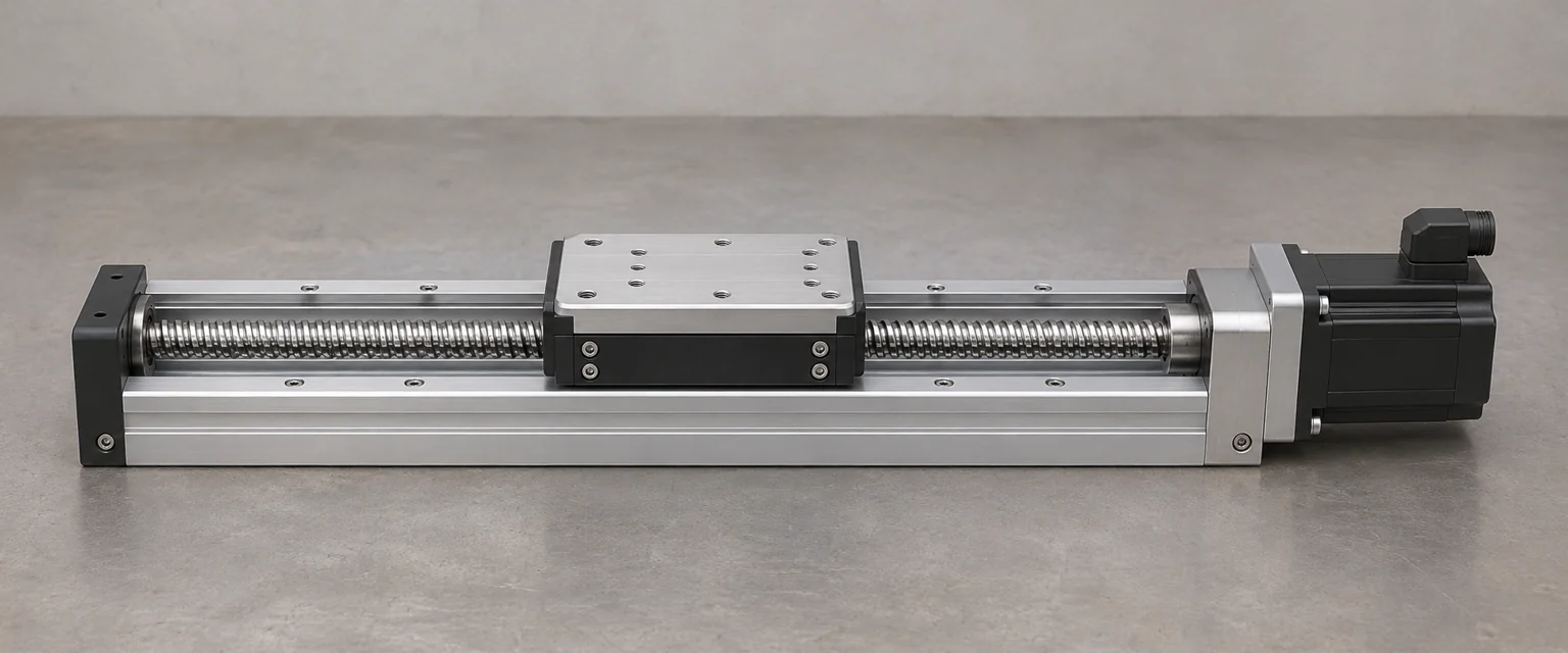
Use a dimensioned envelope, not a stroke label
A supplier’s dimensional drawing may distinguish nominal stroke, mechanical travel, usable travel and a recommended operating range. Ask what each term means for the actual model. Do not assume all suppliers include the same end allowances in a stated stroke.
Parker’s linear actuator catalog separates rod-style and rodless products and gives model-specific dimensional relationships. This illustrates why the correct drawing matters more than a generic length multiplier.
| Dimension or allowance | Question to close |
|---|---|
| Required process travel | What distance must the tool or workpiece actually move? |
| Operating range | Which carriage positions may the production program use? |
| Carriage envelope | What part of the body is occupied by the moving assembly? |
| End and drive structures | Which dimensions are fixed additions to travel? |
| Motor and transmission | Is the motor inline, folded or mounted elsewhere? |
| External services | Where do cables, hoses and lubrication fittings move? |
| Maintenance clearance | Can fasteners and service items be reached after installation? |
Specify the reference point on the carriage used to define position. The carriage center, front face and tool tip describe different coordinates.
A packing example with assumed dimensions
Consider a hypothetical rodless module with 400 mm of required operating travel. Assume its geometry needs a 120 mm carriage envelope and two 50 mm end allowances. The resulting body envelope in this simplified example is 400 + 120 + 50 + 50 = 620 mm.
An inline motor package projecting another assumed 150 mm makes the overall axial envelope 770 mm. Cable bend space and service access can require more installation space outside that envelope.
These are invented layout values, not a formula or dimension for a LIMON model. A real module may define its rated stroke differently or have unequal end structures. Use the actual drawing instead of applying the example as an order-length rule.
The value of the exercise is to expose each allowance. It prevents a designer from reserving a 400 mm machine bay for a 400 mm process move and discovering the drive housing interference during assembly.
Home, limits and stopping space must fit the application
A reference or home position is a coordinate-setting feature. It is not automatically the beginning of unrestricted process travel. Likewise, a mechanical end of travel is not necessarily a suitable routine stopping position.
Review the motion profile, sensing arrangement and machine risk controls with the selected module. Leave the required operating margin inside the physical travel and verify it under the intended speed and load. The appropriate margin is application-specific; a fixed number copied from another machine may be inadequate.
Model the tool as well as the bare carriage. A payload overhanging the carriage can reach an obstruction before the carriage reaches the end of its nominal stroke. The same is true of a hose loop or cable carrier mounted to the table.
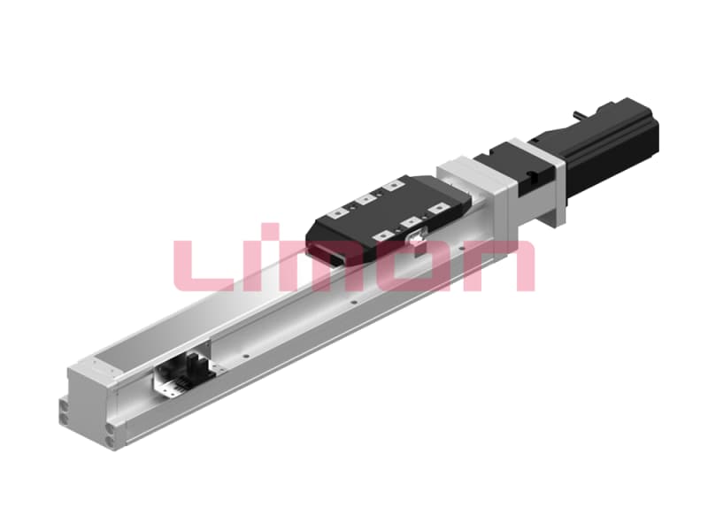
Two carriages change the space calculation
With two mechanically connected carriages, the usable movement depends on their lengths and separation. If their spacing increases to support a longer fixture, less body length remains available for motion unless the module is extended accordingly.
If carriages move independently, check their complete swept envelopes and separation requirements. The sum of two catalog stroke labels does not establish collision-free independent travel. Include the workpiece, tooling and service lines in the interference review.
State whether the enquiry is for one carriage, connected carriages or independently driven carriages. The supplier should not have to infer this from a required load and stroke alone.
Motor orientation can save length while adding width
An inline motor can increase the axial envelope. A folded arrangement may shorten it while occupying additional width or height. Compare complete three-dimensional envelopes, not only the longest dimension.
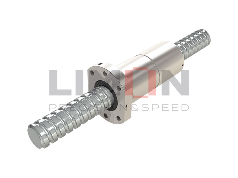
Сайт LIMON GSC 50 page identifies a screw-driven guided module; its actual mounting and dimension options need confirmation for the selected configuration. Use the ball screw axis range to identify candidate families, then request the correct CAD model and drawing.
Also check access to coupling fasteners, motor connectors, lubrication points and module mounting bolts. A package that fits the machine during design may still be difficult to assemble or service.
Drawing package for an OEM quotation
Send the required process travel, allowable length-width-height envelope, carriage reference point, payload geometry, motor orientation and service-line arrangement. Include the speed profile and where the tool must stop relative to the workpiece.
Contact LIMON with a layout drawing and request confirmation of usable travel and complete envelope on the same drawing revision. Keep that approved relationship with the order so a later motor or carriage change also triggers a space review.