Is poor actuator mounting causing binding, uneven travel, premature wear, or unexpected failure in your equipment?
To mount a linear actuator, align it with the load’s direction of travel, secure both ends with compatible brackets and pins, allow pivoting when required, eliminate side loading, verify clearance through the full stroke, connect controls safely, and test the mechanism at low speed before applying the rated load.
This guide covers mounting styles, installation steps, common mistakes, selection, safety, and future-ready actuator design.
What Should You Check Before Mounting a Linear Actuator?
A successful installation begins before the first bracket is attached. Confirm that the actuator is correctly sized for the application and that the machine structure can support the forces created during acceleration, operation, stopping, and load reversal.
Start with the required stroke. The actuator must move the load through its complete working range without reaching its internal limit too early or colliding with surrounding components. Check both the fully retracted and fully extended dimensions, including the mounting brackets and the space needed for cables.
Next, review the following specifications:
- Maximum dynamic load during movement
- Static load when the actuator is stopped
- Required extension and retraction speed
- Stroke length and positioning range
- Duty cycle and expected cycles per day
- Push and pull force requirements
- Horizontal, vertical, or angled orientation
- Environmental temperature and contamination
- Required sealing and corrosion resistance
- Available power supply and control system
- Feedback, limit-switch, and braking requirements
Dynamic load and static load are not interchangeable. An actuator may hold more force while stationary than it can move safely. Acceleration, impact, vibration, and an off-center payload can also create forces significantly greater than the load’s weight.
For vertical applications, determine what happens if power is removed. Do not assume that every screw-driven actuator is self-locking. A brake, mechanical lock, counterbalance, or separate safety device may be necessary to prevent an uncontrolled descent.
Which Linear Actuator Mounting Style Should You Use?
Когда инженеры спрашивают how to mount linear actuator systems correctly, the first decision is whether the actuator needs a pivoting or fixed installation. The mounting style must follow the movement of the mechanism without forcing the actuator to bend.
A clevis mounting arrangement is common for rod-style electric linear actuators. A pin connects the rear mounting point to one bracket, while another pin connects the rod end to the moving load. This allows the actuator to pivot as the mechanism changes angle. Clevis mounting is frequently used for hatches, lifting platforms, agricultural equipment, solar trackers, adjustable machinery, and mobile equipment.
Trunnion mounting supports the actuator through pivot points positioned around its body. It can be useful when installation space is limited or when the actuator must rotate around a point closer to its center.
Some actuator and linear module designs support rigid mounting through body flanges, foot mounts, or dedicated mounting surfaces. Rigid mounting should only be used when the product is designed for it and the machine provides accurate alignment.
In any configuration, the actuator’s force axis should remain aligned with the load. The two mounting pins should be parallel when the mechanism requires rotation in a single plane. If the linkage moves through multiple planes, spherical bearings or suitable rod-end joints may be required.
Mounting brackets must also be strong and stiff enough to resist both the rated actuator force and any shock loads. A weak bracket can deflect under load, turning an initially aligned installation into a side-loaded system.
How Do You Mount a Linear Actuator Step by Step?
Before installation, disconnect the power supply and support any component that could move, fall, or rotate. Never rely on the unmounted actuator to hold a suspended load while you work.
Follow this process:
- Position the actuator. Place it close to the intended operating axis and confirm that the motor, housing, rod, connectors, and cables have sufficient clearance.
- Mark the mounting points. Use the actual retracted and extended actuator dimensions. Do not estimate bracket locations from stroke length alone.
- Install the fixed-side bracket. Attach the rear bracket to a rigid structural surface using fasteners appropriate for the expected load and material.
- Connect the rear mounting point. Insert the correct pin without forcing it through a misaligned bracket. Secure it using the specified retaining hardware.
- Move the mechanism into position. Support the load independently and align the rod-end mounting hole with the moving bracket.
- Attach the rod end. Insert and secure the second pin. The connection should pivot freely where pivoting is required.
- Check the complete travel path. Move the mechanism through its intended range manually where possible, or operate it slowly without the working load. Look for interference, cable tension, binding, and changing alignment.
- Tighten and inspect. Tighten bracket fasteners to the appropriate torque and confirm that retaining clips, locking nuts, and safety devices are installed.
Do not hammer mounting pins into place or pull misaligned brackets together with bolts. Both practices introduce stress before the actuator begins operating. Do not weld close to an installed actuator unless it has been removed or fully protected from heat, electrical current, and weld spatter.
How Can You Prevent Side Loading, Binding, and Premature Wear?
Most rod-style linear actuators are designed to produce force along their centerline. They are not intended to function as the main structural guide for a large or unstable load.
Side loading occurs when force pushes the actuator rod sideways rather than directly along its extension axis. This can result from misaligned brackets, a sagging structure, an unsupported payload, an off-center force, or a linkage that follows an incompatible arc.
Even modest side loading can increase friction between internal components. Possible symptoms include:
- Uneven or jerky movement
- Increased motor current
- Reduced extension or retraction speed
- Excessive noise or vibration
- Inconsistent positioning
- Damaged seals or rod surfaces
- Overheating and unexpected shutdown
- Premature screw, nut, or bearing wear
The most effective solution is to guide the payload independently. Linear guides, guide rails, shafts, or other suitable bearings should carry lateral forces and moments, allowing the actuator to provide axial thrust.
Bracket geometry should also be checked at several positions—not only when the actuator is fully retracted. A linkage may appear aligned at one end of its travel but create severe angular error at the opposite end.
Avoid using the actuator’s end-of-stroke position as a repeated mechanical stop unless the product is specifically designed for that operating method. External stops, properly adjusted limit switches, or controller-based position limits can prevent impact loading.
For long-stroke compression applications, verify buckling resistance. An actuator may have sufficient thrust capacity but still be unsuitable if its extended structure is too slender to remain stable under compression.
How Should You Connect, Test, and Commission the Actuator?
Electrical installation should follow the actuator’s specified voltage, current, wiring, control, and protection requirements. Incorrect voltage, reversed connections, undersized cables, or inadequate circuit protection can damage the motor, controller, feedback device, or internal limit switches.
Before applying power, verify:
- Supply-voltage compatibility
- Cable size and connector condition
- Fuse or circuit-breaker protection
- Polarity and grounding requirements
- Extension and retraction commands
- Limit-switch operation
- Position-feedback wiring
- Emergency-stop functionality
- Motor-current or overload settings
- Protection against cable movement and abrasion
The first powered test should be performed at low speed or in short increments. Keep personnel clear of pinch points and ensure that the payload is independently supported where necessary.
Begin without the full working load. Extend and retract the actuator while listening for unusual noise and watching for bracket movement, structural deflection, cable pulling, and changing alignment. Confirm that the actuator stops before the mechanism reaches an obstruction.
Next, introduce the load gradually. Monitor motor current, speed, temperature, repeatability, and mounting stability. A current level that rises significantly at one position may indicate binding or misalignment rather than insufficient actuator capacity.
After the initial operating cycles, switch off and secure the system, then inspect the mounting pins, fasteners, brackets, retaining hardware, and cables again. Rechecking the installation after its first production period can reveal settling or loosening before it becomes a reliability problem.
Electrical and safety-critical work should be completed or reviewed by appropriately qualified personnel.
How Do You Choose an Actuator and Mounting System for Future Requirements?
A good mounting design should meet today’s operating conditions while leaving reasonable capacity for future changes. Replacing a light payload with a heavier tool, increasing cycle speed, or extending production hours can significantly change the demands placed on the actuator.
For horizontal movement, required force typically includes rolling or sliding resistance, acceleration force, process force, and an appropriate safety margin. For vertical movement, the system must also overcome the load’s weight. Linkages, hinges, and lifting arms require additional attention because actuator force changes with mounting angle.
A simplified relationship is:
Required force = Load-related force + Acceleration force + Process resistance + Safety allowance
The worst operating angle—not the easiest position—should determine the required force. An actuator connected close to a hinge may need substantially more thrust than the lifted load’s weight suggests.
Future-ready selection should consider:
- Expected increases in load or cycle rate
- Higher positioning or repeatability requirements
- Feedback and closed-loop control
- Condition monitoring
- Current and temperature protection
- Integration with machine controllers
- Maintenance access
- Replaceable mounting components
- Environmental changes
- Energy consumption over the actuator’s life
Smart actuators can provide position, current, temperature, voltage, and cycle information. This data can help protect equipment and support predictive maintenance, but connectivity does not compensate for poor mechanical installation. Accurate alignment, suitable guidance, strong brackets, and correct sizing remain the foundation of reliable motion.
Why Choose Limon for Your Linear Actuator System?
A linear actuator is only as reliable as the complete system around it. Actuator force, stroke, speed, duty cycle, mounting geometry, guidance, brackets, controls, and operating environment must work together.
Limon is a linear motion product manufacturer with a fully integrated production line. This manufacturing capability helps us maintain consistent quality and respond efficiently to different industrial application requirements.
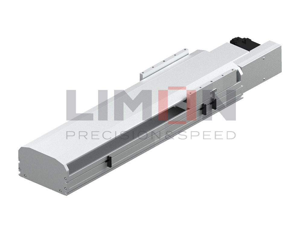
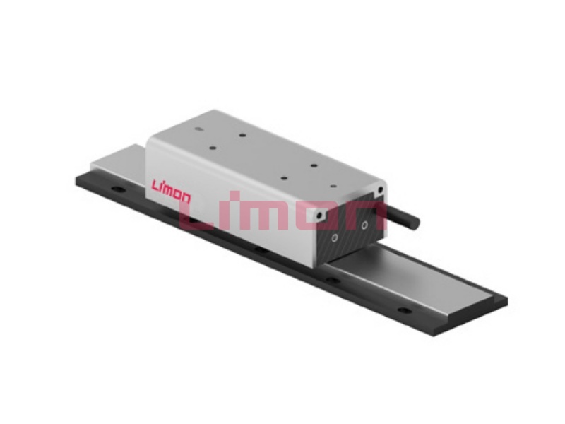
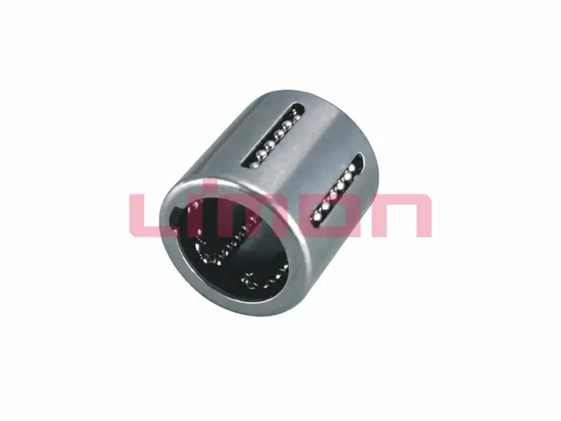
Our product range includes linear actuators, linear guides, ball screws, and linear bearings. Customers can therefore source both the driving and guiding components of a linear motion system from one experienced manufacturer.
Limon’s direct-sales model also creates a clearer route between the customer and the technical team. Instead of selecting an actuator based only on a short product description, customers can discuss important application details such as:
- Load and force direction
- Required stroke and speed
- Рабочий цикл
- Ориентация при монтаже
- Доступное место для установки
- Условия окружающей среды
- Feedback and control requirements
- Linear guidance needs
This direct communication helps reduce selection errors and makes customization discussions more efficient. Whether you are building automation equipment, an adjustable workstation, a lifting mechanism, a production machine, or a mobile system, Limon can help identify a reliable and practical linear motion solution.
Заключение
Correct actuator mounting requires more than attaching two brackets. The actuator must be properly sized, aligned with the direction of force, protected from side loading, given sufficient travel clearance, connected safely, and tested throughout its complete operating range.
Independent linear guidance, rigid mounting structures, suitable pivot points, and careful commissioning can significantly improve accuracy and service life. With integrated manufacturing, dependable quality, direct sales, and professional technical support, Limon provides reliable, high-performance linear motion solutions for demanding industrial applications.
Ready to Install a More Reliable Linear Actuator System?
Visit the Limon independent website to explore our linear actuators, linear guides, ball screws, and linear bearings.
Send the Limon technical team your load, stroke, speed, duty cycle, mounting orientation, available space, and environmental requirements. We will help you select an actuator and supporting linear motion components suited to your application.