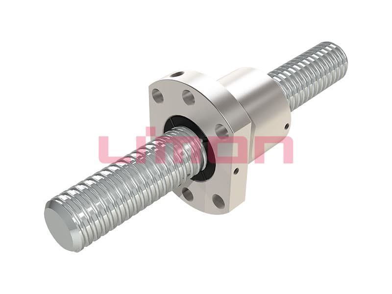
A ball screw end-machining drawing should define the bearing seats, locating shoulders, locknut thread, drive extension and their relationships to the screw axis. Overall length alone is not enough. The drawing must show how the screw fits the support bearings and coupling without trapping an unintended axial load in the assembly.
For an OEM quotation, provide the mating support-unit and coupling drawings with the screw drawing. A standard end designation is useful only when its exact dimensions and revision are understood by both parties.

Start with the bearing arrangement
Identify which end establishes the screw’s axial location and what function the opposite end performs. A fixed-supported assembly and a fixed-fixed assembly require different interface decisions. Mark the drive end and identify whether a drive extension is required at one end or both.
Thomson’s end-machining explanation describes the bearing journal and shoulder as essential interfaces, and distinguishes these from the drive extension. Those functions should remain separate in your drawing even when several features are machined in one setup.
Use the chosen ball screw support units as the starting point for bearing-seat dimensions. Do not size a bearing journal from the nominal screw diameter alone. The available root section and the required bearing shoulder must also be reviewed.
An interface checklist for the drawing
| Характеристика | Information to specify | Mating part or inspection reference |
|---|---|---|
| Fixed-end journal | Diameter, fit, seat length and finish | Bearing bore and approved fit specification |
| Locating shoulder | Axial position, contact diameter and corner clearance | Bearing inner-ring seating geometry |
| Locknut feature | Thread size, pitch, usable length and relief | Locknut and locking method |
| Drive extension | Diameter, engagement length and connection feature | Coupling, pulley or other transmission |
| Opposite-end seat | Diameter, seat length and intended axial freedom | Supported-end bearing arrangement |
| Axial stack | Distance between functional shoulders | Bearing and housing stack-up |
| Geometric controls | Datum system and permitted runout relationships | Defined inspection setup |
Use the fit and surface-finish requirements approved for the actual bearing and connection. A general note saying “precision finish” does not define an inspectable requirement. Likewise, a tight journal diameter does not automatically establish acceptable shoulder runout.
Choose datums that reflect how the screw works
The functional screw axis and bearing seats must be related in a way that can be manufactured and inspected. Agree on how the inspection setup establishes the reference axis and where runout will be measured. A supplier cannot infer this reliably from several unrelated diameter tolerances.
For axial dimensions, use functional shoulders as references where appropriate. Avoid a long chain of end-to-end dimensions that leaves the bearing stack dependent on accumulated tolerances. If a dimension is reference-only, mark it accordingly so it is not mistaken for a second, conflicting requirement.
Do not assign geometric tolerance values simply because they appeared on another screw drawing. Relate them to the bearing arrangement, required axis performance and achievable inspection method.
Review the coupling connection separately
A coupling bore needs both the correct diameter and enough engagement length. Check where its hub will sit relative to the locknut, bearing housing and motor shaft. Ensure the hub does not bottom against an unintended shoulder or bridge a relief groove.
If a keyway, flat or thread is required, identify its length and location. A longer keyway is not automatically an improvement; it changes the local shaft section and may create an unwanted interference. Consider access for assembly tools and later removal while the mechanism is still on the drawing.
For a belt or pulley drive, include the radial load and overhang in the design review. An end extension designed only for a direct coupling may need a different bearing and shaft assessment when it also supports a pulley.
Check the axial stack before releasing production
As a review exercise, trace the assembly from the fixed housing through its bearing pair, screw shoulder and locknut. Identify what clamps what, and where the axial reaction returns to the machine frame. Then trace the opposite support and locate any intended freedom for thermal growth.
If the same dimension both sets bearing preload and accommodates an uncertain housing stack, stop and resolve the arrangement. Bearing preload, ball-nut preload and any screw pretension are separate design quantities. They should not be hidden under one drawing note such as “assemble tight.”
Where fixed-fixed and fixed-supported arrangements are under comparison, close the support concept before finalizing the end dimensions.
Specify what will be inspected
For each critical interface, identify the dimension, datum and measurement method. Journal diameter may require a suitable micrometer; geometric runout needs the agreed support and indicator arrangement. Keep the inspection requirement consistent with how the feature functions.
Include the screw and nut model, lead, usable travel, overall length, thread direction, preload or clearance requirement, end-treatment requirements and drawing revision. If a nut is already assembled, specify the protection and handling arrangement during machining and shipment.
Enquiry package for a custom assembly
Send LIMON’s ball screw team the dimensioned drawing, support-unit references, coupling drawing, quantity and operating requirements. If you are starting from an SFNU-series assembly, identify the full code instead of assuming every shaft with the same diameter uses the same end treatment. Ask for dimensional confirmation before approving repeat production.