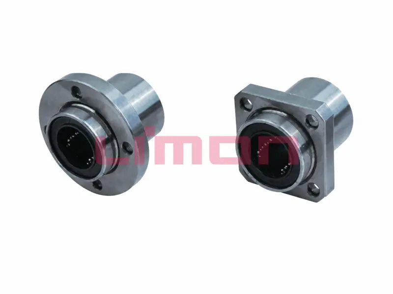
A linear bushing has two fits to check. The shaft runs inside the ball rows, while the outer sleeve sits in the housing. A loose housing fit can still produce an axis that binds if the shaft is too large or the housings pull it out of line. Choose the two fits with the bearing drawing in hand and verify running clearance after assembly.
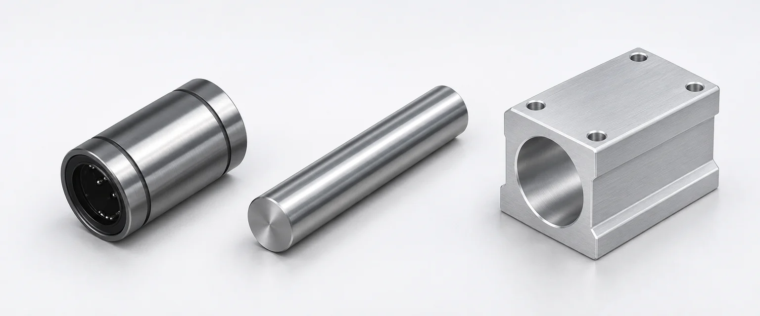
Start with the running clearance you need
Find the full bearing code, including any clearance or adjustable sleeve suffix. Then locate the shaft outside diameter and housing bore recommendations for that model. Uppercase fit letters refer to the hole and lowercase letters to the shaft. A housing callout such as H7 therefore belongs on a different surface from a shaft callout such as g6.
THK's linear bushing assembly tables show why those choices belong together. For its high accuracy LM models, the normal-clearance shaft options include f6 and g6, with h6 listed for a smaller gap. The LME entries use different shaft recommendations. Those are examples for the models in that table. For a LIMON assembly, check the current LM series drawing o LME series drawing and request the fit guidance for the selected suffix.
Put both interfaces on the inspection drawing
| Surface or feature | What the drawing and inspection record should show |
|---|---|
| Shaft running diameter, d | Final upper and lower limits after grinding or coating, measurement positions and running length |
| Housing bore, D | Final diameter limits and form requirements, with the mounting and clamping condition recorded |
| Bushing outer sleeve | The corresponding outer diameter limits from the selected bearing drawing |
| Shaft and housing datums | How to check coaxiality along one shaft or alignment between paired shafts and housings |
| Retention features | Shoulder or ring locations and insertion relief, tied to the bearing's effective seating length |
For a quick check of the housing-to-sleeve fit, subtract the sleeve outside diameter from the bore. Suppose the bore limits are 28.000 to 28.015 mm and the sleeve limits are 27.990 to 28.005 mm. The worst-case diametral difference ranges from −5 µm to +25 µm. That pairing can arrive as either a small interference or a clearance fit. The calculation covers the outside fit. The clearance between the shaft and ball rows comes from the bearing geometry, shaft size and the way the sleeve deforms when retained.
Inspect after the housing is fastened
A thin housing can change bore shape when tightened to the carriage. If the bushing runs freely on the shaft before installation but tightens once the housing is bolted down, check bore form and alignment under that assembled condition. Check the bearing retention as well. THK shows ring and plate arrangements for its standard sleeves and warns that a set screw pressing directly against one side can deform the sleeve. An adjustable sleeve calls for the housing and adjustment method intended for that model.
Measure the final shaft and bore after their specified surface treatments. Where the machine runs warmer than the inspection room, consider the temperature of each component and its restraint. Aluminum and steel expand at different rates, and the sign of a small fit can change with temperature. Keep the temperature at which your measurements were taken with the inspection record.
Finish with a full-stroke resistance check and the relevant clearance or deflection measurement under a documented test load. Compare the results before and after the housings are finally tightened. If the running surfaces are being specified at the same time, see how shaft hardness affects bushing life. For replacements, the LM and LME dimensions comparison helps identify the correct sleeve family before you assign tolerances.
Send the bearing code, shaft and housing drawings, mounting condition and desired clearance with a LIMON fit enquiry. Include any bore readings taken after assembly if a current design is binding.